background image

ACM700x-­‐2-­‐LMx   Quick   Start   (520084-­‐Rev   1.1)   

Page   1


ACM7004-­‐2-­‐LMA


ACM7004-­‐2-­‐LMCR


ACM7008-­‐2-­‐LMA


ACM7004-­‐2-­‐LMV


ACM7004-­‐2-­‐LMCT


ACM7008-­‐2-­‐LMV


ACM7008-­‐2-­‐LMR


Quick Start Guide 


Thank  you  for  purchasing  the  Opengear  Resilience  Gateway  (referred  to  herein  as  the 

appliance

).  This  Quick  Start  walks  you  through  installation,  configuration  &  local 

operation. More details are available in the 

User Manual

, which can be downloaded from: 

http://opengear.com/documentation


Step   1    Check   kit   contents   


Resilience Gateway appliance; e

xternal rack m

ount tab; 

black

 terminal block; t

wo 4G LTE blade antennas; dual 

SIM holder; DB9F-RJ45 adapter (319015, to DTE); four 
rubber feet; 12VDC power pack; Quick Start Guide.


Step   2    Connect   the   hardware


Ø


Attach rubber feet to base, or attach the rack mount tab 

Ø


Screw the antennas on to the   

(M) 

main and   

(A)

 diversity connectors – if 

you have an optional GPS antenna, screw it on to the   GPS connector
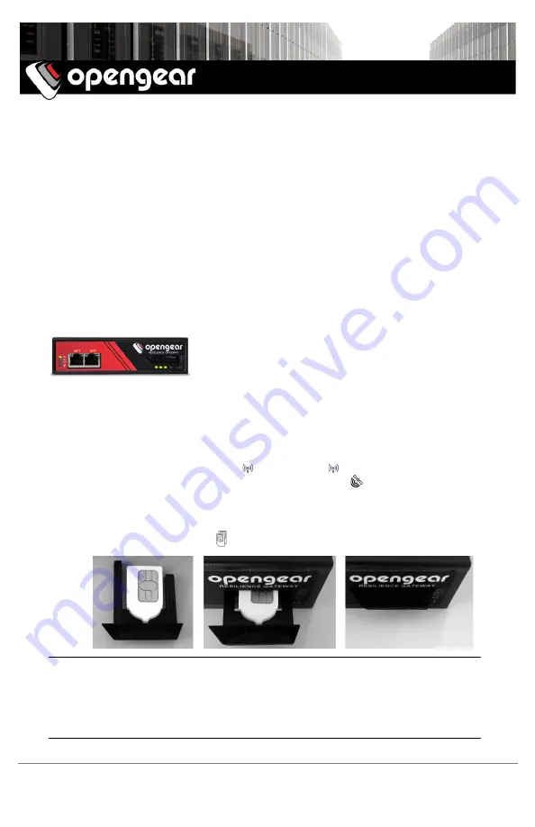
 

Ø


Using  a  standard  size  Mini-SIM  (2FF)  card, 

insert  the


notched  side  firmly 

into the bottom slot of the SIM holder, with contacts facing upwards


Ø


Insert the holder into the   Dual SIM slot, with


longer guide arm to the left


Note:


The -LMA, -LMV, -LMCR and -LMCT models include Opengear 

OCM 

cellular 

modem  devices,  which  are  programmable  to  support  either  AT&T  USA,  Verizon  USA, 
Rogers Canada or Telus Canada. The -LMR with 

OCM73R4

 supports most other carriers 

globally, including major carriers in EMEA, APAC and ANZ regions.  For more details, refer 
to  the 

Knowledge  Base  FAQ

  article 

OCM  modem  devices  integrated  in  ACM7000 

Resilience Gateways

Ø


Connect the Ethernet 

NET1

 port to your primary network


Summary of Contents for ACM7004-2-LMA

Page 1: ...t the hardware Ø Attach rubber feet to base or attach the rack mount tab Ø Screw the antennas on to the M main and A diversity connectors if you have an optional GPS antenna screw it on to the GPS connector Ø Using a standard size Mini SIM 2FF card insert the notched side firmly into the bottom slot of the SIM holder with contacts facing upwards Ø Insert the holder into the Dual SIM slot with long...

Page 2: ...uter that is connected to the appliance via NET1 Ø Enter https 192 168 0 1 into the address bar Ø Log in using the default system user name root and the default password default a Welcome screen listing the basic configuration steps is displayed Note The computer must have an IP address in the same network range 192 168 0 x as the appliance The appliance also has DHCP client enabled by default It ...

Page 3: ...ed with your cellular carrier Ø Select Status Statistics then the Failover Out of Band tab Ø Verify the Connection Status of Internal Cellular Modem is Connected and note your allocated IP Address take note if it s a private IP address Ø At any time you may view the cellular signal strength RSSI from the Cellular tab of the Status Statistics page an RSSI of 100 dBm and less is unacceptable coverag...

Page 4: ... traffic to a downstream Ethernet router o Check Enable and select Internal Cellular Modem as the Modem o Select Management LAN as the Interface o If your router has issues accepting the cellular network settings via DHCP check Enable Force Subnet Mask and enter Force Subnet Mask of 24 o To access to the appliance itself e g for OOB management using the cellular IP address check Intercept Enabled ...

Reviews: