


User’s Guide
omega.com
e-mail: [email protected]
For Latest Product Manuals
omegamanual.info
®
®
Shop on line at
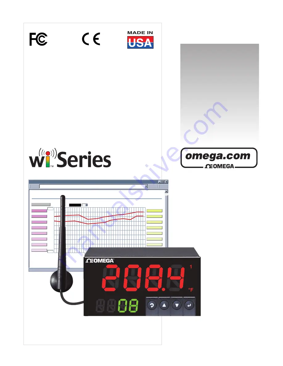
Wireless Meter Scanner & Controller
wiSeries
Main Menu
CHART
(2 Seconds/Div)
1 Minute
1 Minute
1 Day
1 Week
1 Month
1 Year
0
5
C/Div
50
1200
300
100%
0%
10
%/Div
90
hPa/Div
C
hPa
Tue Feb 5 10:19:10 PDT 2008
Tue Feb 5 10:18:10 PDT 2008
http://192.168.1.200
Min/Max Temperature
48.0/41.0
P1 Process
P2 Sensor 2
P3 Process
P4 Process
P5 Process
P6 Process
P7 Process
P8 Sensor 8
A1 Ambient
A2 Sensor 2
A3 Ambient
A4 Ambient
A5 Ambient
A6 Ambient
A7 Ambient
A8 Sensor 8
Save Current Graph


