Olympus X-Tr, Repair Manual
The Olympus X-Tr Repair Manual is a comprehensive user guide designed to assist users in troubleshooting and fixing any issues with their Olympus X-Tr camera. This essential manual is available for free download at manualshive.com, providing users with the necessary knowledge and step-by-step instructions for seamless repairs.
Share
Download


Reviews:
No comments
Related manuals for X-Tr

DTX 500 LCD
Brand: Levenhuk Pages: 76
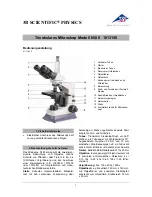
N180 1013150
Brand: 3B SCIENTIFIC PHYSICS Pages: 24

Luxeo 6i
Brand: Labomed Pages: 27

FuraLED
Brand: Cairn Pages: 4

LSM 710 SIM
Brand: Zeiss Pages: 22

RB50
Brand: Fein Optic Pages: 21

M827TL Series
Brand: Omax Pages: 18

SOP003
Brand: CMi Pages: 11

T-1754
Brand: Ken A Vision Pages: 2

PrepScope T-1252
Brand: Ken A Vision Pages: 2

Microprojector 2
Brand: Ken A Vision Pages: 2

PupilCAM 1402KEM
Brand: Ken A Vision Pages: 4

PrepScope T-1201
Brand: Ken A Vision Pages: 4

T-1922C
Brand: Ken A Vision Pages: 8

Professor Stereo ESH200
Brand: Ken A Vision Pages: 8

Dual Purpose Scope 2 T-19311C
Brand: Ken A Vision Pages: 8

Dual Purpose Scope 2
Brand: Ken A Vision Pages: 8

kena T-1050
Brand: Ken A Vision Pages: 16


