Olympus HST-Lite, User Manual
The Olympus HST-Lite is a high-quality camera with advanced features for stunning photography. Ensure optimal performance by downloading the free User Manual from manualshive.com. This comprehensive manual will guide you through setup, usage, and maintenance, maximizing your photography experience with the Olympus HST-Lite.
Share
Download


Reviews:
No comments
Related manuals for HST-Lite

CanoScan LiDE 120
Brand: Canon Pages: 2

easy-scan
Brand: Easy Pix Pages: 2

DLL5000 Series
Brand: Datalogic Pages: 16

1097
Brand: Technology Solutions Pages: 25

KIP 600
Brand: Katsuragawa Electric Pages: 28

ITNS-400
Brand: it Pages: 28

KOJAK
Brand: iB Pages: 20

DocuMate 6710
Brand: Xerox Pages: 76

Nuvera 200
Brand: Xerox Pages: 2

Multiscan
Brand: Hanatech Pages: 189

XCARD-SCAN
Brand: Xerox Pages: 68
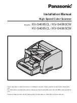
KV-S4085CL
Brand: Panasonic Pages: 24

AV810C
Brand: Avision Pages: 50

Travel Scanner 100
Brand: Xerox Pages: 96

MS588
Brand: Unitech Pages: 101

AV121
Brand: Avision Pages: 2

DL-0710H
Brand: Avision Pages: 83

AD3 Series
Brand: Avision Pages: 2


