Olympus CK40M FRAME, Repair Manual
The Olympus CK40M FRAME Repair Manual is available for free download on manualshive.com. This comprehensive manual provides step-by-step instructions for maintaining and repairing your Olympus CK40M FRAME, ensuring optimal performance and longevity. Don't wait, download your manual today and keep your device running smoothly.
Share
Download


Reviews:
No comments
Related manuals for CK40M FRAME

UX1B
Brand: Richter Optica Pages: 10
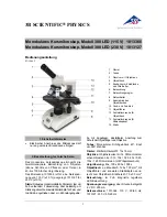
300 LED 1013366
Brand: 3B SCIENTIFIC PHYSICS Pages: 12

Biorit ICD-CS
Brand: Bresser Pages: 12

91-19600
Brand: Bresser Pages: 20

5014000
Brand: Bresser Pages: 28

Eclipse E400
Brand: Nikon Pages: 21

B07TZPQ35P
Brand: AmazonBasics Pages: 13

B07TWLF9Z2
Brand: AmazonBasics Pages: 16

PZ-4
Brand: M2 Pages: 13

LCD Microscope
Brand: National Geographic Pages: 7

STM7
Brand: Olympus Pages: 104

LSM 710
Brand: Zeiss Pages: 23

U-UVF248
Brand: Olympus Pages: 24

Beta Elite 591157
Brand: Wolfe Pages: 8

Ergo 80
Brand: Vision Engineering Pages: 18

HUXSCOPE-WiFi
Brand: TheFibers Pages: 2


