


Reviews:
No comments
Related manuals for CH3-BI45
Geovid 56
Brand: Leica Pages: 2
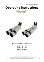
Brightsky 22x70-45
Brand: Omegon Pages: 6

P1026
Brand: Steiner Pages: 46

Geovid 10x42 BRF
Brand: Leica Pages: 2

APO-TELEVID 65
Brand: Leica Pages: 1

APO Televid 62
Brand: Leica Pages: 1

PathFinder 8x42 EXPS
Brand: Olympus Pages: 16

Eddie Bauer
Brand: Bushnell Pages: 1

13-0805
Brand: Bushnell Pages: 1

62-0726
Brand: Bushnell Pages: 8

ImageView 11-0718
Brand: Bushnell Pages: 43

Imageview 11-1025
Brand: Bushnell Pages: 20

121225
Brand: Bushnell Pages: 6

ImageView 118326
Brand: Bushnell Pages: 38

20-1925
Brand: Bushnell Pages: 52

10x50 PIF
Brand: Pentax Pages: 7

10x21UCF R
Brand: Pentax Pages: 11

DiamondBack
Brand: Vortex Pages: 5


