background image


Maintenance Manual


AL120-12 

Series


300mm


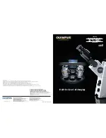
Semiconductor Wafer Loader 


Wafer Loader           

AL120-LMB12-LP3 

AL120-LMB12-F 


Wafer Loader Accessory 

AL120-VS12       
AL120-RC         


Thank you for purchasing the Olympus AL120 Series Wafer Loader. 

In order to fully utilize its performance and secure safety, please read this manual before operation.   

Please also keep it at hand during operation as well as for future reference. 

This manual is exclusively for maintenance service engineer. 

Please also keep it at hand during operation as well as for future reference.


AM5060-01 

Summary of Contents for AL120-12 Series

Page 1: ...chasing the Olympus AL120 Series Wafer Loader In order to fully utilize its performance and secure safety please read this manual before operation Please also keep it at hand during operation as well...

Page 2: ...This page intentionally left blank...

Page 3: ...120 series Stage The AL120 series consists of a wafer loader a vacuum stage and other products This manual does not cover custom order specifications or microscopes To acquire a comprehensive understa...

Page 4: ...such as the power supply unit light source and lamp housing to avoid contact with these heat sources 2 Use the device within the scope of the specifications 3 When you move equipment notify Olympus di...

Page 5: ...ance is required a larger work space can be prepared by changing the observation tube orientation or moving the stage The following installation space is set according to the SEMI standard guidelines...

Page 6: ...Operation Maintenance Manual i 4 Page AL120 LMB12 F extermal view eye point and center of gravity Unit mm AL120 LMB12 F installation space Unit mm Stage movement range installation space Center of gra...

Page 7: ...duction Safety Precautions i 5 Page AL120 LMB12 LP3 extermal view eye point and center of gravity Unit mm AL120 LMB12 LP3 installation space Unit mm installation space Stage movement range Center of g...

Page 8: ...ke Protection Please fix the equipment to the supporting floor so as not to be moved by unexpected force such as an earthquake using stoppers or equivalent means as per the requirements Quakeproof fix...

Page 9: ...rest OLYMPUS distributor for exchange and servicing DANGER MECHANICAL HAZARD KEEP HANDS AND GARMENTS CLEAR OF MOVING PARTS CONSULT MANUAL FOR SERVICING INSTRUCTIONS Warning indications position Each a...

Page 10: ...der using a soft cloth moistened with pure water Wipe heavy dirt or stains with a clean paper moistened with commercially available absolute alcohol Never place absolute alcohol close to a flame as it...

Page 11: ...sition is initialized and the model name is shown on the liquid crystal panel The loader may have been set to skip initialization when the power is turned on This is not a malfunction The loader execu...

Page 12: ...quipment is carrying out evaluation to the guideline of the following SEMI standard S2 1016 Safety Guidelines for Semiconductor Manufacturing Equipment S8 1016 Safety Guidelines for Ergonomics Enginee...

Page 13: ...Operation Maintenance Manual Introduction Conformity Standards i 11 Page...

Page 14: ...Introduction Conformity Standards Operation Maintenance Manual i 12 Page...

Page 15: ...t Programs 3 1 1 How to Use the Programs 3 1 2 To open the door of the FOUP opener of AL120 LMB12 LP3 3 2 3 Test Names and Functions 3 3 4 Replacement of Consumables 4 1 1 Macro Center Table If a vacu...

Page 16: ...Maintenance Manual Table of Contents C 2 Page This page intentionally left blank...

Page 17: ...oader Main Body 1 1 1 AL120 LMB12 F Power Switch Lock ring Joystick EMO Cassette base Operation Panel Warning label Hand guard Warning label A arm Stage operation permission LED F1 arm F2 arm Macro ta...

Page 18: ...menclature Wafer Loader Main Body Operation Maintenance Manual 1 2 Page 1 1 2 AL120 LMB12 LP3 Inspection view window FOUP Opener FOUP opener operation LED Hand guard Opening permission LED of the wind...

Page 19: ...r AL120 LMB12 F 1 1 4 Back part Main Disconnector AL120 LMB12 LP3 Vacuum tube receptacle AC line receptacle Main Disconnector Stage Vacuum tube connector Circuit Breakers Vacuum tube receptacle AC lin...

Page 20: ...FOUP opener operation LED Observation setting buttons Wafer No selector buttons Quit button Auxiliary function buttons Top macro spin direction control Top macro spin speed control Menu buttons Wafer...

Page 21: ...nance Manual Nomenclature Remote Controller Option 1 5 Page 1 2 Remote Controller Option Remote controller AL120 RC Registration setting button Macro Registration setting button Micro Start button Waf...

Page 22: ...Controller Option Operation Maintenance Manual 1 6 Page Vacuum Stage Vacuum stage AL120 VS12 Y fine travel knob X fine travel knob Clutch lever Coarse adjustment grip Wafer rotating knob Stage sensor...

Page 23: ...me thickness to be confirmed into all slots of the cassette 6 Quit adjustment test mode 1 2 Operating Procedure 1 Activate adjustment test mode Turn the main switch OFF Turn the main switch ON while p...

Page 24: ...red in the lowest and highest slots of the cassette and set the cassette in the cassette table The menu appears on the liquid crystal panel M1 Do the mapping adjustment Adjust mapping Press the M1 but...

Page 25: ...tes mapping Mapping M2 Displays the results of mapping senso Display result sensor Make sure that all the slots for each sensor have indication of OK If there are any wafers with an NG indication the...

Page 26: ...arm 0 1mm UP DOWN Moves the A arm slightly down DOWN A arm 0 1mm DOWN Adjust the A arm height so that the A arm is inserted between the wafer to be removed 13th and the wafer below it 12th Press the M...

Page 27: ...Maintenance manual Adjustments 2 5 Page Check the states of the 2nd and 25th wafers in the same way 6 Termination of adjustment test mode Turn the main switch OFF to terminate test mode...

Page 28: ...the cover You can find following vacuum switches U001 Stage table U002 A arm U003 Center table U004 L arm U005 F arm 1 U006 F arm 2 Perform vacuum switch sensitivity adjustment using the testprogram...

Page 29: ...played and the vacuum is maintained Press the Start button to turn the vacuum OFF Use wafer tweezers to prevent the wafer from falling 3 Select a test number with a Wafer No selector button 4 Press th...

Page 30: ...press the Start button while pressing the interlock switch of the FOUP opener the door of the FOUP opener opens Do not release your hand from the interlock switch until the door of the FOUP opener ope...

Page 31: ...ring sensor count check 11 Wafer mapping sensor mapping sensor height check Applicable to AL120 LMB12 F FOUP OPENER mapping sensor parameter setting Applicable to AL120 LMB12 LP3 12 A arm insertion he...

Page 32: ...wafer sensor returns to its initial position and the loader stops the operation M2 Horizontal movement If the loader has not been initialized initialization starts Raises the wafer sensor to the cass...

Page 33: ...oader stops the operation M2 Dock FOUP Dock movement check If the loader has not been initialized initialization starts FOUP Clamp FOUP Undock position FOUP Dock position The loader then repeats steps...

Page 34: ...ation starts FOUP Clamp FOUP Dock position FOUP Door Clamp FOUP Door open FOUP Door close The loader then repeats steps to Do not install the cassette Press the Start button to pause the operation at...

Page 35: ...arting the operation M1 A arm insertion height A arm insertion height Select the operation speed using the menu buttons on the liquid crystal panel M1 High speed Fast speed M2 Medium speed Middle spee...

Page 36: ...release your hand from the interlock switch and press the Start button to are for AL120 LMB12 LP3 only Moves to upper limit height Center of Macro table Cassette side Cassette side Center of Macro ta...

Page 37: ...tialization starts Right side 4mm Origin Left side OriginThe loader then repeats steps to Press the Start button to pause the operation at the break point When an error occurs the loader displays the...

Page 38: ...nger than 5 minutes Wait for longer than one minute before restarting the operation No 6 L arm vertical movement check L arm vertical movement check This program can be used to check the L arm vertica...

Page 39: ...de as in the regular operation and then stops Press the Quit button and the L arm returns to its initial position and the loader stops the operation To save the registered position press the button Me...

Page 40: ...Start button Select the operation speed using the menu buttons on the liquid crystal panel M1 High speed Fast speed M2 Medium speed Middle speed M3 Low speed Slow speed If you do not specify anything...

Page 41: ...and the loader stops the operation No 10 Centering sensor count check Centering sensor count check This program can be used to check the centering sensor count state Press the Start button Initialized...

Page 42: ...llation part the operation does not start Press the 4 way button RIGHT to start initialization in the horizontal direction of the A arm When an error occurs the loader displays the same error code as...

Page 43: ...1 button The mapping is executed If the loader displays that the mapping data is Result OK press the M2 button to register the data M1 Execute the automatic mapping adjustment Adjust mapping M2 Regist...

Page 44: ...another Settable parameters Item Set value Default Number of cassette slots Slot 25 26 25 Slot pitch Pitch 6350 10000 10000 Upper limit of wafer position error Upper 10 to 3000 1500 Lower limit of waf...

Page 45: ...ue from FOUP opener Load default parameter of FOUP opener M4 Write default value to FOUP opener Set default parameter of FOUP opener This test stores the standard values of the thickness thickness tol...

Page 46: ...nput To be used only for the offset start position 4 way buttons RIGHT and LEFT Move the cursor 4 way buttons UP and DOWN Move from one item to another Settable parameters Item Set value Default Numbe...

Page 47: ...d crystal panel to then confirm or adjust the settings M1 Turn the vacuum ON for the A arm Vacuum ON OFF M2 Move the height of the cassette installation part to the removal height or the arm insertion...

Page 48: ...This program can be used to check and adjust the A arm height Press the Start button Select the item to adjust using the menu buttons on the liquid crystal panel M1 Check the origin in backward forwar...

Page 49: ...ed has been inserted The Wafer No button for the selected slot stops blinking and stays lit Press the Start button The selected wafer is loaded from the cassette After centering is performed the wafer...

Page 50: ...ry is displayed on the liquid crystal panel CW CCW 00 Set the notch position setting knob in the direction you want to adjust the notch alignment Correct the notch alignment position Save the correcti...

Page 51: ...t the cassette that contains the wafer Using the 4 way button select the number of wafer type to adjust or register from the list of wafer type numbers displayed on the liquid crystal panel and then p...

Page 52: ...press the Start button to being operation M1 Change the up down position of the A arm A arm change position M2 Change the L arm position L arm change position M3 Change the F arm position arm Showing...

Page 53: ...Stage lock and observation window lock movement check Stage lock movement check Stage and window lock movement check AL120 LMB12 LP3 This program can be used to check the notch sensor and wafer senso...

Page 54: ...n M1 M2 M3 M4 1 A front back cassette position sensor AL cst U205 AL120 LMB12 F lower limit sensor E low U104 E step out sensor E out2 U105 2 A front back standby position sensor AL mid U206 Horizonta...

Page 55: ...type screen at the time of the inspection Wafer thickness Thick 775 500 500 200 Wafer size and thickness settings may be unavailable depending on the loader specifications Transfer speed Speed Fast M...

Page 56: ...on the liquid crystal panel and then press the Start button If the loader has not been initialized initialization starts The mapping is executed and the Wafer No button of the slot that contains the w...

Page 57: ...e button ON ON OFF OFF Setting of slot with which wafer transfer begins in a cassette Start slot Bottom Bottom Top Top Numbering of wafers in a cassette No on wafers in cassette From bottom 1 Bottom F...

Page 58: ...Number of the step in which the error occurred Date and time of error occurrence Date Time The first segment of Software version indicates version of the M CPU board and the second segment indicates...

Page 59: ...Maintenance Manual Test Programs 3 31 Page This page intentionally left blank...

Page 60: ...ug the power cord before replacing consumables Use the right tool for the right accessory when assembling this product If the tools are not used properly or this manual is not followed during assembly...

Page 61: ...eal groove Remove the oil seal by lifting it from the outside pulley side 3 Wind the clean wiper around the flat blade screwdriver Moisten it with commercially available absolute alcohol and clean the...

Page 62: ...er the check attach the macro center table Replacement Cycle 5 years Standard Working Time 20 minutes 3 A arm If a vacuum error has occurred or the A arm vacuum pad has become damaged Tools Phillips h...

Page 63: ...minutes 5 Oil Seal for Vacuum Table If a vacuum error has occurred Tools Phillips head screwdriver No 0 Flat blade screwdriver No 2 6 30 Clean wiper and absolute alcohol 1 Remove the three M2 cross r...

Page 64: ...xis of the vacuum stage Never put absolute alcohol near flames as it is highly flammable Take care not to cause a spark by turning on off electric appliances or fluorescent lamps 5 With the lip facing...

Page 65: ...the L arm vacuum pad 3 Replace the L arm vacuum pad 4 Attach the cover of the L arm vacuum pad Standard Working Time 15 minutes 7 F arm If a vacuum error has occurred or the F arm vacuum pad has becom...

Page 66: ...If wafer transfer sound has increased 1 Remove the stage and replace the rubber blocks on the underside of the microscope Since the wafer transfer position must be checked and other related work must...

Page 67: ...This page intentionally left blank...

Page 68: ...US SCIENTIFIC SOLUTIONS AMERICAS CORP 48 Woerd Avenue Waltham MA 02453 U S A OLYMPUS SINGAPORE PTE LTD 438B Alexandra Road 03 07 12 Alexandra Technopark Blk B Singapore 119968 OLYMPUS KOREA CO LTD 2F...

Reviews: