


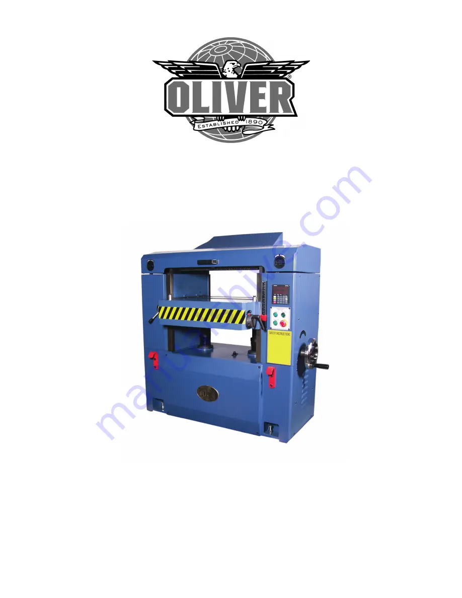
4470 Industrial Planer 2
5
”
Owner’s Manual
Oliver Machinery
M-4470 9/20
17
Kent, WA 98032
[email protected]
Copyright 2003
www.olivermachinery.net
The Oliver 4470 Owner's Manual is a comprehensive guide for operating and maintaining your product. You can easily download the manual for free from manualshive.com. Ensure you have all the information you need to maximize the performance of your Oliver 4470 with this essential manual.
4470 Industrial Planer 2
5
”
Owner’s Manual
Oliver Machinery
M-4470 9/20
17
Kent, WA 98032
[email protected]
Copyright 2003
www.olivermachinery.net


