Oki C3400n, Maintenance Manual
The Oki C3400n is a high-quality printer designed for home and office use. With its sleek design and advanced features, this printer ensures seamless printing experience. To maximize your printer's potential, download the free Spanish Guía Del Usuario manual from manualshive.com, offering detailed instructions, troubleshooting tips, and more.
Share
Download


Reviews:
No comments
Related manuals for C3400n

AP1200
Brand: ABLE Pages: 26

C410
Brand: Xerox Pages: 262

d-Color P221
Brand: Olivetti Pages: 78

ES5460
Brand: Oki Pages: 128

KM-1635
Brand: Kyocera Pages: 13

IP-7900-21
Brand: Oki Pages: 109

CS655
Brand: Oce Pages: 495

CS 4550c
Brand: Copystar Pages: 4

Mira-PJ1
Brand: Ricoh Pages: 70

RXi HMI GFK-3233A
Brand: Emerson Pages: 20

Aficio GX7000
Brand: Ricoh Pages: 5

RJ-900C series
Brand: MUTOH Pages: 8
DP-CL21 Series
Brand: Panasonic Pages: 32
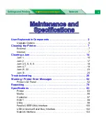
DP-CL21 Series
Brand: Panasonic Pages: 103
2C-POS80-02
Brand: 2connet Pages: 17

Xpress M2835DW
Brand: Samsung Pages: 2

Xpress M2875FD
Brand: Samsung Pages: 2

Xpress M2070FW
Brand: Samsung Pages: 2


