

Installation Instructions
Model Number 1074-PROJ
(877) 867-2312
•
www.oberonwireless.com
Rev. A2 08/18/14
Oberon, Inc.
•
1315 South Allen Street
•
State College, PA 16801
Copyright 2013
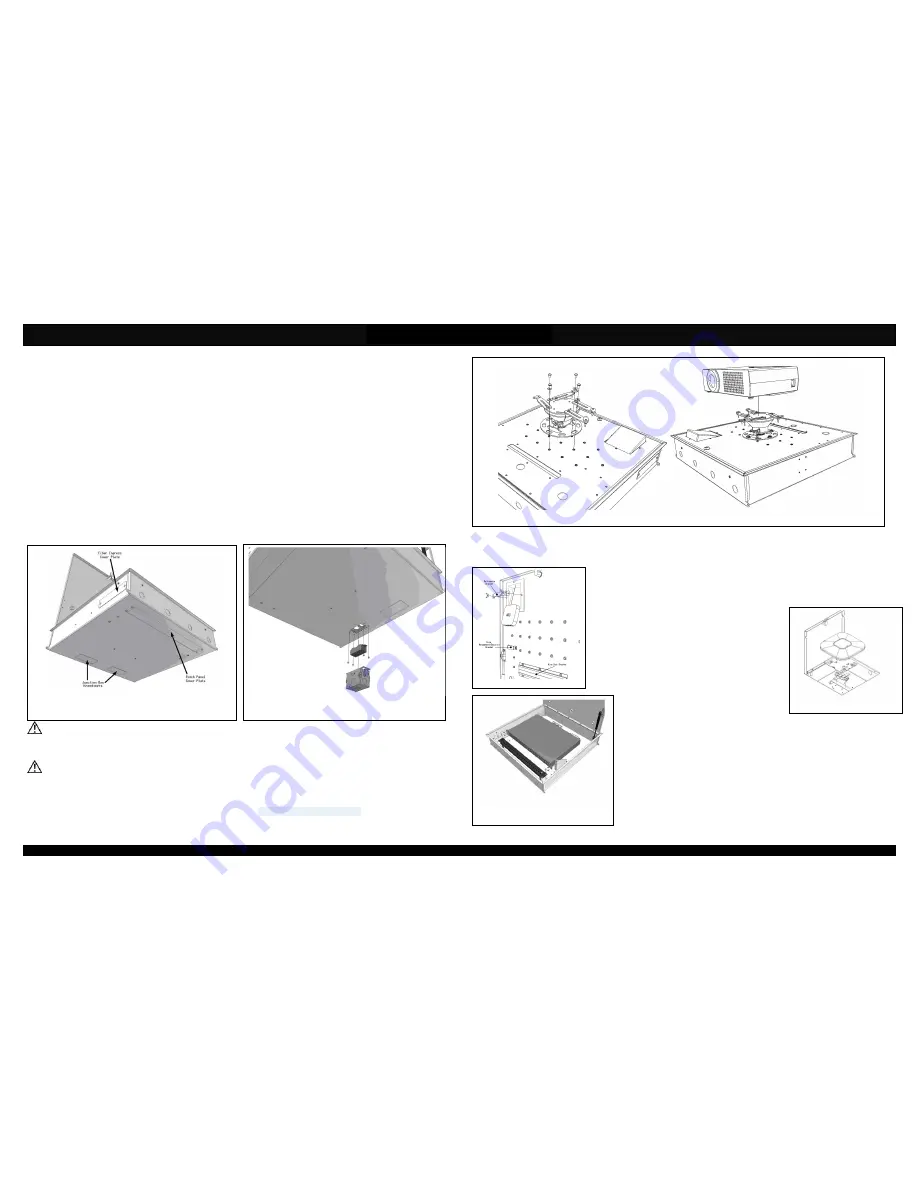
Figure 6
Figure 1
Figure 2
Figure 3
Figure 4
Figure 5
Assembly Components:
- Ceiling enclosure Model 1074-PROJ assembly – 1 each
- Universal Projector Mount – 1 each
- Electrical Junction Box – 1 each
- Electrical Receptacle – 1 each
- Electrical Receptacle Cover – 1 each
- ½” Trade size cable clamps – 1 each
- Fire Block Foam – 2 each
- Support wire –8 each
- Wire Management J-Hook – 1 each
- Self Drilling Screw – 4 each
- Keys for access door lock – 2 each
- #6 – 32 x 3/16 screw – 4 each
- #10 – 32 x 3/8 screw – 4 each
- Installation Instructions – 1 each
If any of these items are missing, contact your Oberon representative.
Find a flat work surface to assemble the multimedia ceiling enclosure and any other network/cellular components prior to mounting in
ceiling.
Step 1 – Place the multimedia ceiling enclosure assembly on the work surface with the door facing up and keyed doorway unlocked. If
applicable, remove patch panel and fiber ingress cover plates (Figure 1) located on the outside edge and back of the box (near key lock)
and install patch panel and CCH style fiber optic adapter panel according to the manufacturer’s specifications.
**IMPORTANT** - If patch panel or adaptor panel are not used, the covers should remain in place.
Step 2 – Attach the electrical junction box to the cutout located near the back of the enclosure (Figure 2) with four (4) #6-32 screws.
**IMPORTANT** - The electrical junction box must be attached to the back box with all four (4) screws for it to be
grounded properly. A power supply outlet MAX 125VAC, 20A should be used.
Step 3 - Prior to installing the projector mount find a suitable location for the enclosure to be mounted in the ceiling. There is a pattern of
holes on the door that allow you to move the mount from side to side giving the installer several inches of freedom to move the projector if
projector screen is not perfectly centered. Install Chief Projector Mount (P/N CHIICPRIA1T03
or
SANVMPR1B) w/ the (4) #10 - 32 screws
provided with the mount (Figure 3). For added security, Chief provides a special hex screw that can only be used with the manufacturers
hex key.
Page 2
Step 4 - The Chief Projector Mount has arms that extend to several different positions (Figure 3). Attach the projector to the Chief Projector
mount according to the manufacturers instructions (provided with the mount). Make sure not to tighten the screws completely because
adjustments may need to be made.
Step 5 - (Optional) Attach any multimedia devices such as the AppleTV
TM
and Roku
TM
with the
bracket provided shown in Figure 4. A piece of foam (provided) should be placed between the
multimedia device and the bracket to provide a secure fit and prevent any damage to the device.
Cable(s) can be run through the wire management/security bracket and attached to the projector by
running it out through the dust brush.
Step 6 – (Optional) Use the manufacturers T-Bar mount clip to
attach the access point to the T-Bar mount inside the
enclosure. An additional mounting plate provided by the
manufacturer of the access point may be needed to attach the
access point (Figure 5). Data cable(s) may need to be plugged
in to the access point prior to attaching to the mount. Cisco
access points use Cisco AIR-AP-BRACKET-2 for 2600/3600
series
access
points
and
AIR-AP-BRACKET-1
for
1140/3500 series.
Step 7 – (Optional) Install all rack mounted equipment to the mounting brackets with four
(4) #10-32 screws. The maximum height the enclosure can accommodate is 2U and the
maximum length is 14”. The mounting brackets can be repositioned to fit networking
equipment of various lengths (Figure 6).
The assembled unit is now ready for ceiling installation.
Page 3


