

© Freescale Semiconductor, Inc., 2004. All rights reserved.
Freescale Semiconductor
Quick Start Guide
Rev. 0.2, 07/2005
DEMO908QB8 Quick Start Guide
Introduction and Default Settings
This kit contains everything you need to get started. This guide will walk you though how to connect the board
to your PC, run the LED test program, install the correct version of CodeWarrior Development Studio, and load
an ATD (Analog to Digital) test program. Source code for DEMO908QB8_LED (LED test) and
DEMO908QB8_ATD (ATD test) are provided on the Axiom CD in the “Examples” folder.
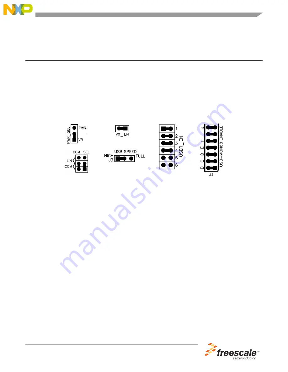
Below are diagrams of the default settings for the DEMO908QB8 demo board. Please refer to the
DEMO908QB8 User’s Guide on the Axiom CD for information on other configurations. Black blocks indicate
the “on” or “installed” position of jumpers. Please check these settings before continuing.
Figure 1
.
DEMO908QB8 Default Settings
Install CodeWarrior Development Studio Version 3.1 for HC(S)08 and USB Drivers
If you do not have version 3.1 of CodeWarrior for HC(S)08 Special Edition installed on your computer, please
refer to the provided “CodeWarrior Development Studio” DVD case and follow the steps in the quick start
guide.
After CodeWarrior has been installed properly, please install the HC(S)08 USB 2.0 service pack
(CW08_V3_1_P&E_USB2_SP.exe) from the CodeWarrior service pack CD. This is required if you want to use
the USB-MON08 feature on the DEMO908QB8 board. The HC(S)08 USB 2.0 service pack can also be
downloaded from www.metrowerks.com
Important:
You must register and obtain a special edition license key to use CodeWarrior. This license key
allows you to experience all the features of the Special Edition CodeWarrior Development Studio.
Run the DEMO908QB8_LED program
The DEMO908QB8 is shipped with the DEMO908QB8_LED program stored in on-chip Flash memory. You
may view the source code for this program by accessing the “DEMO908QB8_LED.zip” file on the Axiom CD
(located in the “Examples” folder).
1.
Check the jumper settings and make sure they are in the default position. Use figure 1 as a guide.
2.
Connect the USB cable to the PC and then to the board. If you are using this board for the first time,
please follow the instructions on the screen to install the USB device properly.
3.
After the USB drivers are installed correctly, the USB, PWR OUT, and +5V LEDs will be on.
4.
Remove jumber B from the USB—MON08 Enable.
5.
Press SW1 and LED1 will turn on. Release SW1 and LED1 will turn off.
6.
Press SW2 and LED2 will turn on. Release SW2 and LED2 will turn off.


