nvent ERICO System 3000, Installation, Operation And Maintenance Manual
The nVent ERICO System 3000 Installation, Operation, and Maintenance Manual is a comprehensive guide to maximizing the performance of your system. This manual is available for free download on our website, providing users with essential information on setup, functionality, and upkeep of this innovative product.
Share
Download


Reviews:
No comments
Related manuals for ERICO System 3000

UR Series N60
Brand: GE Multilin Pages: 574

6P4840
Brand: Magnavox Pages: 60

RELION RET670
Brand: ABB Pages: 102

RELION REX640
Brand: ABB Pages: 132

PT51G36E - 51" PROJECTION TV
Brand: Panasonic Pages: 27

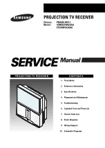
HCR4755WX/XAA
Brand: Samsung Pages: 69
HCN5527WX/XAA
Brand: Samsung Pages: 96

PR512
Brand: ABB Pages: 44

Tyvek 600 Plus CHA5
Brand: Dupont Pages: 20
Bravia KDF-E42A12U
Brand: Sony Pages: 46

8P4831C
Brand: Philips/Magnavox Pages: 50


