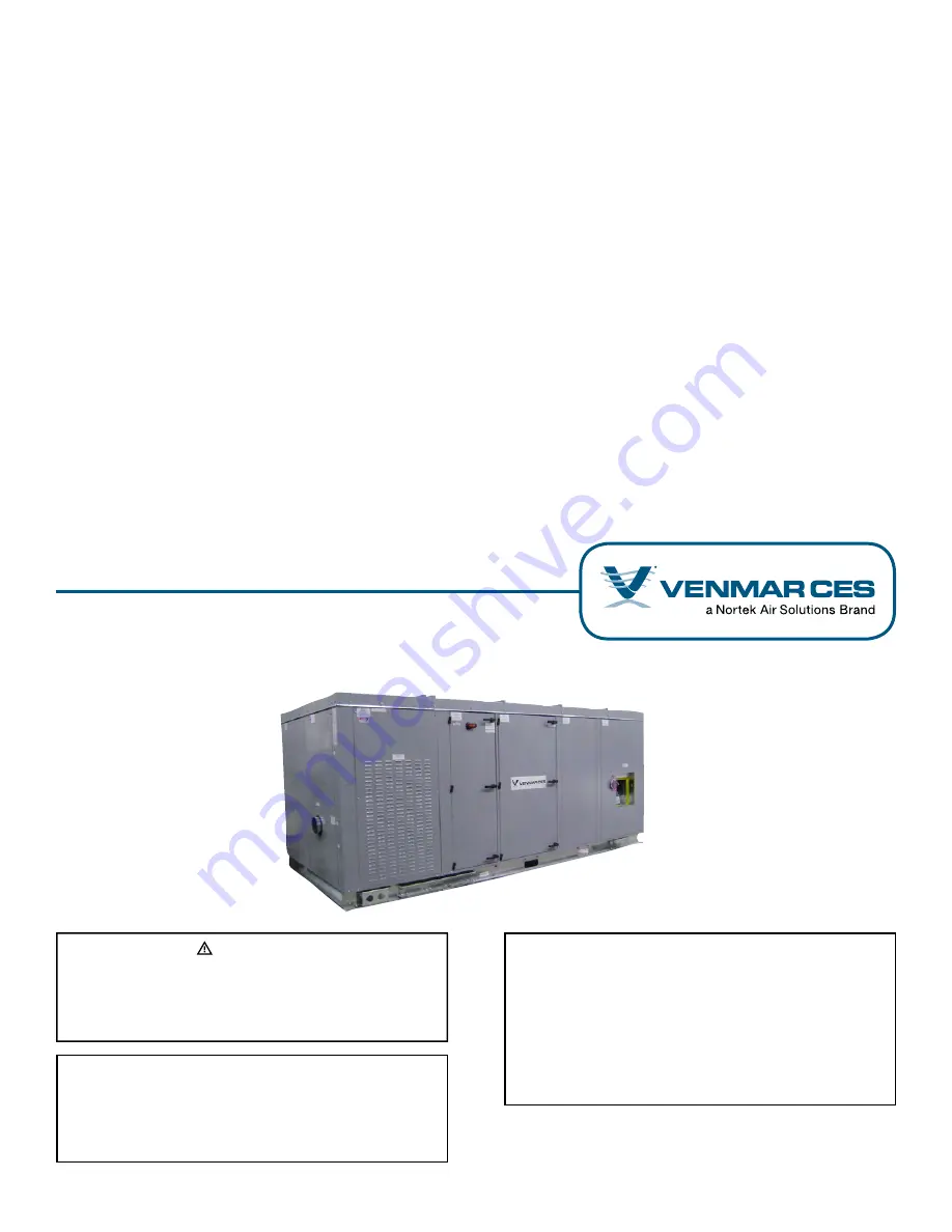
background image

VHC

Energy Recovery Ventilators with Enthalpy Wheels and  
Integrated Heating and Cooling

Installation, Operation and Maintenance Instructions Manual

Capacity: 800 to 5,500 cfm
Model: VHC-36, VHC-42, VHC-50

IMPORTANT

The use of this appendix is specifically intended for a 
qualified installation and service agency. A qualified in-
stallation and service agency must perform all installation 
and service of these appliances.

FOR YOUR SAFETY

What to do if you smell gas:

1.  Open windows if appliance is indoors.
2.  Do not touch electrical switches or use any phone 

in the building.

3.  Extinguish any open flame.
4.  Leave the building immediately.
5.  Immediately call Gas Supplier.

 WARNING

Improper installation, adjustment, alteration, service or 
maintenance can cause injury or death. Read the instal-
lation, operation and maintenance instructions thor-
oughly before installing or servicing this equipment.

Summary of Contents for VENMARCES VHC-36

Page 1: ...rvice agency must perform all installation and service of these appliances FOR YOUR SAFETY What to do if you smell gas 1 Open windows if appliance is indoors 2 Do not touch electrical switches or use...

Page 2: ...ems 24 System Operation Check 25 Appendix A Service Clearance Dimensions 26 Appendix B Hood Installation 34 Appendix C Rigging Drawing 35 Appendix D Equipment Data 36 Appendix E Effect of Undersized S...

Page 3: ...anies Venmar Select from Nortek Air Solutions Variable Refrigerant Control VRC from Nortek Air Solutions and Tefzel from DuPont Nortek Air Solutions LLC d b a Venmar CES furnishes equipment pursuant t...

Page 4: ...red All documentation that was specifically designed for your unit has been included in the pocket of the control panel including if applicable Electrical schematics VHC 36 42 and 50 DDC Controls Pack...

Page 5: ...to flow into internal drains The foundation must provide adequate continuous sup port to minimize deflection of the unit base frame to not more than 1 16 1 6 mm over entire length In addition to these...

Page 6: ...upplied by Others Roofcurbs supplied by others must be designed with the same dimensions and cross member arrangement as per Venmar CES roofcurb drawings and must be designed to evenly withstand perim...

Page 7: ...on and are 6 mm smaller outside of frame than the duct size listed The motorized dampers are for flanged to duct installation and are the same size as the duct size listed inside of the damper frame T...

Page 8: ...al 1 000 fpm outlet velocity to the length of the straight portion of discharge duct The equivalent duct diameter is equal to square root of 4ab Pi where a and b are the rectangu lar dimensions of the...

Page 9: ...pendix B A quick connect for the damper motors is provided to connect to the main body of the unit Make sure that all screws are secured to maintain proper support and keep seals water tight Access Pa...

Page 10: ...pendix G which runs through the outside casing and requires a liquid tight connector or conduit to avoid water penetration Should the Electrical Contractor decide to run the power feed cable through t...

Page 11: ...nd defrost will initiate based on the setpoint Unoccupied Recirculation Ur If the unoccupied recirculation contact closes or a jumper is placed across terminals FW 305 306 the unit will turn off unles...

Page 12: ...e connections is recommended to be installed in the water line for balancing and service Before connecting piping to the unit the water supply line and return line must be flushed to eliminate the for...

Page 13: ...drains annually at start of cooling sea son Drainage problems can occur should drains be inac tive and dry out or due to reduced water flow caused by buildup of algae Regular maintenance will prevent...

Page 14: ...n minimum clearance and the dis charge is not blocked 10 Check that the water strainer has been installed for a water source heat pump with a brazed heat exchanger 11 Check that ductwork is connected...

Page 15: ...er if equipped opens after exhaust air damper opens exhaust blower starts occupied recirculation damper opens outside and exhaust air dampers modulate to the damper minimum setpoints 5 Check that damp...

Page 16: ...ventilation control ac cessory or field supplied by connecting normally open high speed contacts to the supply and exhaust fan high speed input terminals for two speed High Low ventila tion control se...

Page 17: ...electric heating coil and the enthalpy wheel The electric heating coil is selectable in 1 kW incre ments and available in two stage four stage or SCR con trol With staged control one stage cycles to...

Page 18: ...more than 15 The FMS should be located downstream from straight sections of duct and not immediately after fans or obstructions that will cause turbulent flow Refer to Appendix K for optional gas fir...

Page 19: ...ilters and optional high efficiency filters are disposable and should be replaced every three months More frequent replacement may be required under extremely dirty operating conditions To replace the...

Page 20: ...ctor from the motor 1 Figure 5 Loosen the two adjustment bolts 2 Figure 5 on the base plate Rotate the motor and base plate to remove the belt Remove the four bolts 3 Figure 5 and slide the motor asse...

Page 21: ...ch as isopropyl alcohol Insert the bushing into the fan making sure the mating hub is flush against the shoulder at the flats Posi tion the assembly at the desired location on the motor shaft and hand...

Page 22: ...1 Figure 9 from the bearing on the drive motor side of the cas sette Remove the bolt 2 Figure 9 from the end of the wheel shaft with a socket or wrench on the drive motor side Repeat this procedure fo...

Page 23: ...e drive motor See Appen dix Q for belt tensioning and replacement instructions The multi link belt is factory set for proper tension but should it need a tension adjustment simply remove one of the li...

Page 24: ...conditions hence a suitable cleaning schedule should be arranged based on experience and knowledge of the building or local water supply loop Coils Dirt on the surface of the coil reduces its ability...

Page 25: ...s leaving the evaporator and the pres sure in the evaporator the thermostatic expansion valve can control the refrigerant gas leaving the evaporator at a pre determined superheat Three forces that gov...

Page 26: ...or return damper Exhaust rilters Control box Power line input control wiring Electric post heat Cooling heating coil Supply blower 36 0 914 34 0 864 46 0 1 168 Electric pre heat 34 0 864 Standard cass...

Page 27: ...er Exhaust filters Electric post heat Control box Cooling heating coil Supply blower Power line input control wiring 36 0 914 Electric pre heat 46 0 1 168 56 0 1 422 Standard cassette removal 34 0 864...

Page 28: ...return damper Exhaust filters Control box Electric post heat Power line input control wiring 36 0 914 Supply blower Cooling heating coil 56 0 1 422 Standard cassette removal 34 0 864 46 0 1 168 Clear...

Page 29: ...ake hood For indoor units Vent termination and combustion air intake must comply with the National Fuel Gas Code Z2223 1 NFPA54 in the U S in Canada to the Gas Installation Code Can CGA B149 See Acces...

Page 30: ...8 Clearance for enthalpy wheel removal Clearance for S OA intake hood Clearance for S EA hood For indoor units Vent termination and combustion air intake must comply with the National Fuel Gas Code Z2...

Page 31: ...haust filters Control box Compressor Coaxial coil WSHP module Supply blower Electric post heat Power line input control wiring 36 0 914 Water inlet and outlet connections Note All dimensions in are mi...

Page 32: ...blower Cooling heating coil 34 0 864 46 0 1 168 Electric pre heat Supply filters Defrost or unoccupied recirc damper 34 0 864 Enthalpy wheel Occupied recirc or return damper Exhaust filters Exhaust bl...

Page 33: ...Cooling heating coil Supply blower Electric post heat Control box Power line input control wiring 36 0 914 Standard cassette removal 56 0 1 422 34 0 864 46 0 1 168 Electric pre heat Clearance for enth...

Page 34: ...IMPORTANT Complete wire connections between the unit and the hood by matching the correct wire colors on the actuator with the wire colors on the schematic Figure B1 Outdoor VHC hood installation VCE...

Page 35: ...n even vertical lifting force only at all the lifting points to prevent damage to the unit casing 2 Provide additional blocking and coverings as required to prevent damage to the unit finish and or co...

Page 36: ...90 w g 0 20 to 0 90 w g 0 30 to 1 00 w g Filters Supply and return 2 51 mm MEF MERV 8 30 35 1 of 20 x 20 508 x 508 mm 1 of 16 x 20 406 x 508 mm 1 of 18 x 24 457 x 610 mm 1 of 24 x 24 610 x 610 mm 4 o...

Page 37: ...bow position B pressure drop x 1 25 b Elbow position D pressure drop x 0 85 c Elbow position A and C pressure drop x 1 00 Position D Position C Position B Position A Inlet effective duct length Figure...

Page 38: ...local building codes WARNING All units equipped with two point electric post heaters require two point power connections one to the con trol panel and one to the electric heater circuit breaker mounte...

Page 39: ...0 On off 33 3 17 9 12 8 VRC 33 3 17 9 12 8 12 On off 48 1 18 6 14 7 VRC 48 1 18 6 14 7 14 On off 51 3 23 1 19 9 VRC 51 3 23 1 19 9 16 On off 55 8 26 9 23 7 VRC 55 8 26 9 23 7 21 On off 30 4 24 6 VRC A...

Page 40: ...Amperage RLA Compressor Tonnage Cooling Type Voltage 208 230 1 60 208 230 3 60 460 3 60 575 3 60 Water Cooled Single Circuit 2 Two stage 15 3 11 6 5 7 4 0 3 Two stage 17 9 14 2 6 2 4 Two stage 28 8 16...

Page 41: ...rather be selected such that the actual MOP is at least equal to the calculated total MCA Table F5 Dual Circuit Compressors For Dual Circuit On Off Units 6 tons Two 3 ton on off compressors 8 tons Two...

Page 42: ...IRTY SUPPLY FILTER OPTIONAL DIRTY EXHAUST FILTER OPTIONAL WHEEL FAILURE OPTIONAL EXHAUST BLOWER ON COIL LOW LIMIT OPTIONAL 24 VAC OUTPUTS 20 VA MAXIMUM SUPPLY BLOWER ON HEATING ON OPTIONAL COOLING STA...

Page 43: ...ries for con nection to internal coils selected 24 VAC 24 VAC SUPPLY BLOWER MODULATING SHIELD OPTIONAL EXHAUST BLOWER MODULATING 0 10 VDC OPTIONAL SUPPLY BLOWER MODULATING 0 10 VDC OPTIONAL SUPPLY BLO...

Page 44: ...e quire a dry contact which could be provided by a number of types of controls such as a timer light sensor occu pancy sensor building management system or other The unit will not operate unless these...

Page 45: ...could also be the following DPST switch de humidistat CO2 sensor light sensor heat sensor timer building management system etc 301 302 304 305 305 306 307 308 320 321 322 323 324 325 326 327 328 329...

Page 46: ...o NFPA 90A and IMC Code 606 VHCs can be equipped with a duct mount smoke de tector which will monitor the air when passing through the duct system into the VHC When sufficient smoke is detected an ala...

Page 47: ...sors are factory set to close contacts at 0 8 w c 200 Pa 301 302 304 305 305 306 307 308 320 321 322 323 324 325 326 327 328 329 DIRTY SUPPLY FILTER 24 VAC OUTPUTS 20 VA MAXIMUM DIRTY EXHAUST FILTER...

Page 48: ...compressor start up and remain open five seconds after the compressor is shut off IMPORTANT Water source heat pump external water supply and return piping shall be in accordance with national and loc...

Page 49: ...ature which will shut down the compressor and unit for freeze protection The flow switch also features an adjustment which allows the user to change the switch from normally open NO to nor mally close...

Page 50: ...016468S 500027836 19 400 1 12 36 8 7 400 201909070S 500027838 37 400 1 14 42 7 3 400 201909070S 500027838 37 400 1 16 44 3 8 400 201909070S 500027838 37 400 1 Dual circuit 6 18 4 7 400 500016468S 5000...

Page 51: ...int Nominal voltage 24 VAC 50 60 Hz Nominal voltage range 19 2 28 8 VAC Power consumption 1 W Transformer sizing 1 VA Class 2 power source Electrical connection Screw terminals accessible after remova...

Page 52: ...A B 1 69 42 mm 3 22 82 mm Figure I3 Indoor three way valve actuator 6 to 8 tons Table I9 Indoor Three way Valve Actuator Technical and Dimensional Data 6 to 8 tons Power supply 24 VAC 20 50 60 Hz 24 V...

Page 53: ...nches DN mm A B C 1 32 mm 3 96 100 6 2 21 56 2 2 14 54 3 1 40 mm 4 39 111 6 2 45 62 2 2 33 59 1 2 50 mm 4 90 124 5 2 68 68 0 2 60 66 0 Table I13 Indoor Three way Valve Actuator Technical and Dimension...

Page 54: ...ve actuator 10 to 21 tons Table I15 Outdoor Three way Valve Actuator Technical and Dimensional Data 10 to 21 tons Power supply 24 VAC 20 50 60 Hz 24 VDC 10 Power consumption Running Holding 2 5 W 0 4...

Page 55: ...able wrench across the hexagonal or flat faces on the valve body If assembling valve train on bench take care not to deform the body with a vise 1 input 2 outputs Coil Return Supply B A AB Figure I11...

Page 56: ...ly closed To change the switching from normally open to normally closed loosen but do not remove the two screws on the top cap Slide the reed switch assembly to expose the switch action se lected Tigh...

Page 57: ...n and Maintenance Instructions Manual and the VHC 36 42 and 50 DDC Controls Package Manual if equipped before proceeding Leave a copy of this report with the Owner and at the unit for future reference...

Page 58: ...for WSHP with brazed heat exchanger 11 Is ductwork connected and complete 12 Are condensate drain connections trapped installed correctly and filled 13 Are all shipped loose or field supplied componen...

Page 59: ...ulation mode adjust outside air and exhaust air damper positioner to achieve the required air volume 8 Re check the voltage at the disconnect switch against the nameplate and against phase to phase re...

Page 60: ...perature F db wb Outdoor entering Supply enthalpy wheel entering Supply enthalpy wheel leaving Cooling coil leaving Heating coil leaving Re heat coil leaving Supply leaving Return entering Exhaust ent...

Page 61: ...ure F Electric heating Stage 1 2 3 4 5 6 Amp draw L1 Amp draw L2 Amp draw L3 This unit has been checked out and started according with the above procedures and completed forms and is operating satisfa...

Page 62: ...This page intentionally left blank VCES VHC IOM 1F VHC 36 42 50 62...

Page 63: ...ng the gas furnace into service 1 Gas supply provided matches the gas type marked on the furnace module rating plate the gas supply line has been completed according to the Gas Sup ply Piping and Conn...

Page 64: ...t the flue gas discharge path see Figure I1 Where sufficient clearance for proper horizontal venting cannot be provided or in jurisdictions requiring a 4 foot separation between flue gas discharge and...

Page 65: ...nace must be connected to a separate factory built chimney or vent complying with a recognized stan dard or a masonry or concrete chimney lined with a mate rial acceptable to the authority having juri...

Page 66: ...vent deg radation of building material by flue gases The vent terminal must be located at least 1 foot 305 mm above grade or in snow areas at least 3 feet 1 m above snow line to prevent blockage Addit...

Page 67: ...the furnace control en closure which must be field extended to the exterior of the cabinet The gas supply line feeding more than one furnace must be checked for size relative to the connection at each...

Page 68: ...to ensure that the operating air temperature rise is above the dew point temperature of the flue gases in all appli cations and below the maximum allowable air tem perature rise to limit the furnace t...

Page 69: ...m where the temperature is uniform and make the proper adjustments Figure K10 Vertical airflow configuration WARNING Operation of the furnace module at vent temperatures below that specified for a Cat...

Page 70: ...8 Turn gas control knob to On position 9 Open all manual gas valves 10 Turn power on at disconnect switch 11 For start up temporarily set the DDC Control Sys tem for heating and to its highest positi...

Page 71: ...flue gas recirculation into combustion air supply Increase air opening size or re direct flue products to pre vent recirculation d Reduced air delivery can also be the result of fan blade slippage dir...

Page 72: ...uced circulating airflow over the heat exchanger Reduced airflow can be caused by motor failure of the circulating air blower dirt blockage or restriction of the air inlet or outlet to the unit The hi...

Page 73: ...tch APS 1 closes a 15 second pre purge period begins 6 At end of pre purge period the spark commences and the gas valves both first and second stage are energized for the trial for ignition period 7 B...

Page 74: ...will check that pressure switch contacts are open IC terminal PSW is not powered 4 Combustion blower is then energized at high speed 5 When the air switch APS1 closes a 15 second pre purge period beg...

Page 75: ...efer to Table K3 for further LED code troubleshooting MH Sequence of Operation 20 100 Modulation with Two speed Controller Fenwal 35 61 Series Direct Ignition Control TR1 Timer Relay Control and SC30...

Page 76: ...in 0 8 seconds The spark will be energized for a trial for ignition period to attempt to re light burners and prove flame sensor If flame is re established normal operation resumes 2 If the burners fa...

Page 77: ...n proper wheel attachment proper voltage to blower 1 Flash Airflow fault Pressure switch contacts in closed position for 30 seconds with no output to combustion blower Remains in this mode with combus...

Page 78: ...is energized Is spark present If no check igniter for debris between electrodes cracked ceramic and check ignition wire for short to ground Check flame sensor wiring connections to electrode and contr...

Page 79: ...e only wires suitable for 167 F 75 C Wires shall be sized according to the Canadian Electrical Code require ments All wires must be brought in through knockouts 2 4 Disconnecting Means Install a disco...

Page 80: ...inspec tion This precautionary step will help to keep your instal lations operating well Note these eventual first signs of problems Accumulation of dust on the heating elements Signs of overheating...

Page 81: ...dard 0 000256441 0 000224715 50 x 8 high 0 000164571 0 000144459 0 5 0 6 0 7 0 8 0 9 1 0 1 1 1 2 1 3 0 4 0 3 0 1 0 2 0 0 0 500 1 000 1 500 2 000 2 500 3 000 Airflow cfm Pressure Drop in w g 36 x 8 Sup...

Page 82: ...erailment off drive pulley or failure Drive pulley Check for securely fastened pulley on motor shaft Motor and blower not functioning Electrical supply interrupted Check unit circuit breaker Fan motor...

Page 83: ...plication range Refrigerant overcharge Charge correct amount of refrigerant Non condensable air accumulates in the coaxial coil Vacuum system re charge refrigerant Coaxial coil scaled Clean coaxial co...

Page 84: ...rt and grease accumulation Clean as necessary Do not use any caustic cleaning solutions x 21 Examine fan housings and motor pedestal for corrosion Clean and touch up with paint as necessary x 22 Check...

Page 85: ...ettings x 43 Verify system operation in all control modes x Notes 1 Check filters weekly after initial start up until construction dust has been cleared and to gauge required interval 2 Check set scre...

Page 86: ...1 960 63 1 620 64 2 720 47 2 380 52 1 960 53 3 200 37 2 800 40 2 300 42 Grease type NLGI 2 Lithium complex grease Fan Model ATL1 12 12 ATL1 15 11 ATL1 18 13 Class T2 T2 T2 Bearing Size 1 3 16 1 3 16 1...

Page 87: ...humb 4 Ensure tab returns to position across belt Reverse belt so tabs run inside Installation 1 Turn belt with tabs to the inside before installing 2 Determine direction of drive rotation 3 Align bel...

Page 88: ...us V belts require the maintenance of correct drive tension to operate efficiently Experience indicates that drive tension should be checked after 24 hours running at full load A retension may be nece...

Page 89: ...R2 Subtract the measured liquid line temperature from the saturated tempera ture to determine the liquid sub cooling 4 Compare calculated sub cooling to Table R1 for the appropriate unit type and opt...

Page 90: ...G F PSIG F PSIG 20 78 3 47 134 7 74 213 7 101 321 0 128 463 2 21 80 0 48 137 2 75 217 1 102 325 6 129 469 3 22 81 8 49 139 7 76 220 6 103 330 2 130 475 4 23 83 6 50 142 2 77 224 1 104 334 9 131 481 6...

Page 91: ...BH 250 MBH 300 MBH 350 MBH 1 500 1 600 94 1 1 700 88 5 1 800 83 6 1 900 79 2 2 000 75 2 94 1 2 100 71 7 89 6 2 200 68 4 85 5 2 300 65 4 81 8 2 400 62 7 78 4 94 1 2 500 60 2 75 2 90 3 2 600 57 9 72 3 8...

Page 92: ...73 4 4 200 44 8 53 7 62 7 71 7 4 300 43 7 52 5 61 2 70 0 4 400 42 8 51 3 59 9 68 4 4 500 41 8 50 2 58 5 66 9 4 600 40 9 49 1 57 2 65 4 4 700 40 0 48 0 56 0 64 0 4 800 39 2 47 0 54 9 62 7 4 900 38 4 46...

Page 93: ...ons Canada Inc VCES VHC IOM 1F PN 216013 March 2015 Nortek Air Solutions has a policy of continuous improvement and reserves the right to change design and specifications without notice info venmarces...

Reviews: