Nordcap 433000106, User Manual
The Nordcap 433000106 is a high-quality kitchen appliance that will take your cooking to the next level. Ensure optimal performance by downloading the free User Manual from our website. This manual will guide you through the setup and operation of your appliance, ensuring a hassle-free experience every time.
Share
Download


Reviews:
No comments
Related manuals for 433000106

WRL 200
Brand: AERMEC Pages: 32
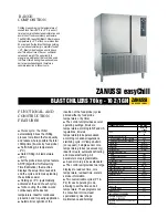
ZANUSSI Easychill 110046
Brand: Zanussi Pages: 3

ZANUSSI easyChill BCFW061
Brand: Zanussi Pages: 4
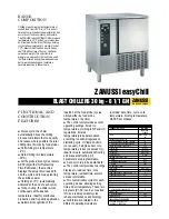
ZANUSSI easyChill 110043
Brand: Zanussi Pages: 3

ZANUSSI easyChill 110022
Brand: Zanussi Pages: 4

BLC-1/2
Brand: Glastender Pages: 20

200037
Brand: Haden Pages: 16

16DF013
Brand: Carrier Pages: 12

ULTRACOOL UC 14
Brand: Lauda Pages: 34

TE70O
Brand: Toyama Pages: 64

RAPID RDA S Series
Brand: Vaderstad Pages: 118

YD Mod D
Brand: York Pages: 160

418121
Brand: Poulan Pro Pages: 22

BC-003UC
Brand: Randell Pages: 17

917.242484
Brand: Craftsman Pages: 24

3.75 HP 17 INCH TINE WIDTH 917.2922
Brand: Craftsman Pages: 32

247.299341
Brand: Craftsman Pages: 64

EWAQ016CAW
Brand: Daikin Pages: 40


