background image


Nokia C5-03  

RM-697, RM-719  


Service Manual Level 1&2 


Conf idential | Copyright © 2011 Nokia | All rights reserved 

Version 3.0 


SERVICE MANUAL 

Level 1&2 


   RM-697, RM-719 


Transceiver characteristics 


Band: 

RM-697 

GSM 850/900/1800/1900 

WCDMA 900/1900/2100 


RM-719 

GSM 850/900/1800/1900 

WCDMA 850/1900/2100


Display: 

nHD 3.2” 640x360 touch screen with 16M colors 


Camera: 

5.0 Mpix full focus camera, 3x digital zoom  


Operating System: 

Symbian OS v.9.4 


Connections: 

3.5 mm AV connector, micro


USB connector,


Micro SD 

memory card slot (up to 16 GB), Bluetooth version 2.0 

with EDR, FM radio receiver with RDS, DC jack


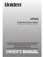
Transceiver with BL-4U battery pack 

 Talk time 

 Standby 

 GSM:  

 Up to 11.5 hours 

 WCDMA: 

 Up to 4.7 hours 

 GSM:  

 Up to 600 hours 

 WCDMA: 

 Up to 588 hours 

Note: 

Talk times are dependent on network parameters  

and phone settings


Summary of Contents for C5-03

Page 1: ... nHD 3 2 640x360 touch screen with 16Mcolors Camera 5 0 Mpix full focus camera 3x digital zoom Operating System Symbian OS v 9 4 Connections 3 5 mm AV connector micro USB connector Micro SD memory card slot up to 16 GB Bluetooth version 2 0 with EDR FM radio receiver with RDS DC jack Transceiver with BL 4U battery pack Talk time Standby GSM Up to 11 5 hours WCDMA Up to 4 7 hours GSM Up to 600 hour...

Page 2: ...ed Version 3 0 Table of contents 1 COPYRIGHT 4 2 WARNINGS AND CAUTIONS 5 2 1 WARNINGS 5 2 2 CAUTIONS 5 3 ESD PROTECTION 6 4 CARE AND MAINTENANCE 7 5 BATTERY INFORMATION 8 6 EXPLODED VIEW 9 7 SERVICE DEVICES 10 8 SOFTWARE UPDATE 11 9 DISASSEMBLY INSTRUCTIONS 12 10 ASSEMBLY HINTS 19 11 SOLDER COMPONENTS 23 ...

Page 3: ...ice to NOKIA products This Service Manual is to be used only by authorized NOKIA service suppliers and the content of it is confidential Please note that NOKIA provides also other guidance documents e g Service Bulletins for service suppliers follow these regularly and comply with the given instructions While every endeavor has been made to ensure the accuracy of this document some errors may exis...

Page 4: ...ght to make changes and improvements to any of the products described in this document without prior notice Under no circumstances shall Nokia be responsible for any loss of data or income or any special incidental consequential or indirect damages howsoever caused The contents of this document are provided as is Except as required by applicable law no warranties of any kind either express or impl...

Page 5: ...HONE MUST NOT BE OPERATED IN AREAS LIKELY TO CONTAIN POTENTIALLY EXPLOSIVE ATMOSPHERES EG PETROL STATIONS SERVICE STATIONS BLASTING AREAS ETC 3 OPERATION OF ANY RADIO TRANSMITTING EQUIPMENT INCLUDING CELLULAR TELEPHONES MAY INTERFERE WITH THE FUNCTIONALITY OF INADEQUATELY PROTECTED MEDICAL DEVICES CONSULT A PHYSICIAN OR THE MANUFACTURER OF THE MEDICAL DEVICE IF YOU HAVE ANY QUESTIONS OTHER ELECTRO...

Page 6: ...ers ESD protection must be applied All electronic parts of the product are susceptible to ESD Resistors too can be damaged by static electricity discharge All ESD sensitive parts must be packed in metallized protective bags during shipping and handling outside any ESD Protected Area EPA Every repair action involving opening the product or handling the product components must be done under ESD prot...

Page 7: ...e damaged Do not store the phone in hot areas High temperatures can shorten the life of electronic devices damage batteries and warp or melt certain plastics Do not store the phone in cold areas When it warms up to its normal temperature moisture can form inside which may damage electronic circuit boards Do not drop knock or shake the phone Rough handling can break internal circuit boards Do not u...

Page 8: ...ing the product switched on until it turns itself off or by using the battery discharge facility of any approved accessory available for the product Do not attempt to discharge the battery by any other means Use the battery only for its intended purpose Never use any charger or battery which is damaged Do not short circuit the battery Accidental short circuiting can occur when a metallic object co...

Page 9: ...L3 A2 FRONT COVER I0002 DISPLAY I0005 EARPIECE I0013 CHASSIS I0015 AV JACK I0012 EARPIECE ADHESIVE I0014 DC JACK I0011 TOUCH PANEL I0001 BOTTOM CAP I0004 KEYMAT I0003 CAMERA I0008 TYPE LABEL I0007 LIGHT SWAP PWB I0006 IHF SPEAKER I0009 ANTENNA MODULE I0010 SCREW TORX 6 I0016 BATTERY COVER I0017 A2 LIGHT SWAP PACKAGE I0006 I0007 A4 CHASSIS ASSEMBLY I0011 I0015 A3 ANTENNA MODULE ASSEMBLY I0009 I0010...

Page 10: ...n 3 0 7 SERVICE DEVICES BL 4U Battery CA 101D AC 8 Travel Charger SS 88 Camera Removal tool Nokia Standard Toolkit v2 For more information refer to the Service Bulletin SB 011 on Nokia Online Supplier or manufacturer contacts for tool re order can be found in Recommended service equipment document on Nokia Online ...

Page 11: ...vice Manual Level 1 2 11 Confidential Copyright 2011Nokia All rights reserved Version 3 0 8 SOFTWARE UPDATE Flash concept Point of Sale Please check always for the latest version of flash software which is available on Nokia Online ...

Page 12: ...CTIONS 1 Nokia C5 03 disassembly 2 For disassembling you need the Nokia Standard Toolkit version 2 the camera removal tool SS 88 an AV plug and a DC plug 3 Protect the TOUCH PANEL with protective film 4 Lift up the BATTERY COVER from the release notches to detach it 5 Remove the BATTERY COVER 6 If there is a battery inserted remove it also ...

Page 13: ...ted remove it also 8 Use the SS 93 to detach the shown clip of the BOTTOMCAP 9 Repeat the procedure on the other side 10 Remove the BOTTOMCAP Do not use it again Discard it 11 Unscrew the four TORX size 6 screws in the order shown 12 Use the SS 93 to detach the three shown clips of the FRONT COVER ASSEMBLY Be careful not to damage any nearby components ...

Page 14: ...5 Hold the FRONT COVER ASSEMBLY as shown Be careful not to damage the flexes 16 Disconnect the TOUCH PANEL connector with the SS 93 Be careful not to damage any nearby components 17 Open the lock of the DISPLAY connector with the SS 93 as shown Be careful not to damage any nearby components 18 Carefully move the FRONT COVER ASSEMBLY away from the CHASSIS so that the DISPLAY connector is disconnect...

Page 15: ...on 3 0 19 Use the SS 93 to carefully detach the DISPLAY fromall sides 20 Lift the DISPLAY away from the FRONT COVER ASSEMBLY 21 Protect the DISPLAY with protective film 22 Protect also the TOUCH PANEL from the inside with protective film 23 Use the SS 93 to detach the KEYMAT 24 Remove the KEYMAT with the tweezers ...

Page 16: ...rst ENGINE BOARD clip Be careful not to damage any nearby components 26 Repeat the procedure on the second clip 27 Lift the ENGINE BOARD from the detached side to protect the side keys 28 Remove the ENGINE BOARD 29 Position the SS 88 camera removal tool on top of the CAMERA and press it down 30 Lift up the SS 88 with the CAMERA and remove the CAMERA ...

Page 17: ... 0 31 To detach the ANTENNA MODULE ASSEMBLY carefully bend the CHASSIS as shown Push the ANTENNA MODULE ASSEMBLY up from the other side 32 Remove the ANTENNA MODULE ASSEMBLY 33 Lever up the DC JACK with the DC plug as shown 34 Remove the DC JACK 35 Lever up the AV JACK with the AV plug as shown 36 Remove the AV JACK ...

Page 18: ... to detach the EARPIECE Be careful not to injure yourself with the sharp end of the dental tool 38 Remove the EARPIECE with the tweezers Discard it 39 Loosen the EARPIECE ADHESIVE with the dental tool 40 Detach the EARPIECE MESH with the tweezers and remove it Do not use it again 41 Nokia C5 03 disassembly is now complete END OF DISASSEMBLY ...

Page 19: ... assembly 2 For assembling you need the Nokia Standard Toolkit version 2 3 Remove the protective film from the EARPIECE ADHESIVE 4 Place the EARPICE ADHESIVE to its place with the tweezers 5 Press down with the SS 93 to activate the EARPIECE ADHESIVE 6 Place the EARPIECE with the tweezers and push it down with the SS 93 to activate the adhesive ...

Page 20: ...n its place 8 Place the DC JACK with the tweezers and push it down with the SS 93 to lock it in its place 9 Place the ANTENNA MODULE with the tweezers 10 Press ANTENNA MODULE down from the shown places with the SS 93 to lock up the clips 11 Place the CAMERA MODULE with the tweezers Make sure that the guiding notch is correctly placed 12 Press the CAMERA MODULE down with the SS 93 Be careful not to...

Page 21: ...e DISPLAY and the FRONT COVER Place the DISPLAY to the FRONT COVER and make sure that it is correctly aligned 16 Make sure the connector isn t locked and push the DISPLAY connector to is place Be careful not to damage the connector or any nearby components 17 While holding the FRONT COVER up lock the connector by pressing the lever down with the SS 93 Be careful not to damage the connector or any ...

Page 22: ...ips 20 Tighten the four TORX size 6 screws to the torque of 14 Ncm in the order shown 21 Place the KEYMAT to its place and make sure its correctly placed 22 Push the BOTTOMCAP to its place Make sure that the shown clips are locked up correctly 23 Insert the BATTERY and place the BATTERY COVER to its place Press it gently to lock up the clips 24 Nokia C5 03 assembly is now complete END OF ASSEMBLY ...

Page 23: ...Nokia C5 03 RM 697 RM 719 Service Manual Level 1 2 23 Confidential Copyright 2011Nokia All rights reserved Version 3 0 11 SOLDER COMPONENTS ...

Reviews: