Nokia 6310, Service Manual
The Nokia 6310 is a classic mobile phone known for its reliability and durability. With a sleek design and user-friendly interface, this device offers seamless communication. Enhance your experience by downloading the user manual for free from our website, providing you with detailed instructions for an optimal user experience.
Share
Download


Reviews:
No comments
Related manuals for 6310

30Z
Brand: TCL Pages: 22

SPH-I300SS
Brand: Samsung Pages: 22

PhoneEasy 618
Brand: Doro Pages: 68

UC840(P)
Brand: Hanlong Pages: 2

D7A
Brand: 2N Pages: 180

Infobar C01
Brand: AU Pages: 96

KX TPA 65
Brand: Panasonic Pages: 14

CVXK-G419
Brand: chinavasion Pages: 6

28223EE1
Brand: GE Pages: 2

Cell Fusion 28129FE2
Brand: GE Pages: 2

Cell Fusion 28127FE1
Brand: GE Pages: 2

30784
Brand: GE Pages: 42

27909FE1
Brand: GE Pages: 2

Cell Phone 28127FE1
Brand: GE Pages: 1

28225 Series
Brand: GE Pages: 54
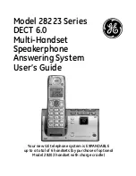
28223 Series
Brand: GE Pages: 68

28861
Brand: GE Pages: 88

iDEN i1000-A
Brand: Motorola Pages: 98


