

Required mounting parts:
Dear customer,
Congratulations on choosing the Noctua NH-U9 TR4-SP3.
Having received more than 300 awards and recommendations
from international hardware websites and magazines, the NH-U9
line has become a benchmark for compact 92mm single tower
coolers. The TR4-SP3 version is a tailored custom model for AMD’s
TR4/SP3 platform and features a larger contact surface as well
as the latest SecuFirm2™ mounting system for socket TR4/SP3.
Enjoy your NH-U9 TR4-SP3!
Yours sincerely,
Roland Mossig, Noctua CEO
This manual will guide you through the installation process of the
SecuFirm2™ mounting system step by step.
Prior to installing the cooler, please consult the compatibility list
on our website (www.noctua.at/compatibility) and verify that
the cooler is fully compatible with your motherboard.
Please also make sure that your PC case offers sufficient clear-
ance for the cooler and that there are no compatibility issues
with any other components (e.g. tall RAM modules). Double
check that the heatsink and fan clips do not make contact with
the VGA card or other PCIe cards.
Noctua cannot be held responsible for any damage or losses
caused by compatibility issues.
Should you encounter any difficulties, please check the FAQs on
our website (www.noctua.at/faqs) and don’t hesitate to contact
our support team at [email protected].
Multilingual versions of this manual are available on our website:
www.noctua.at/manuals
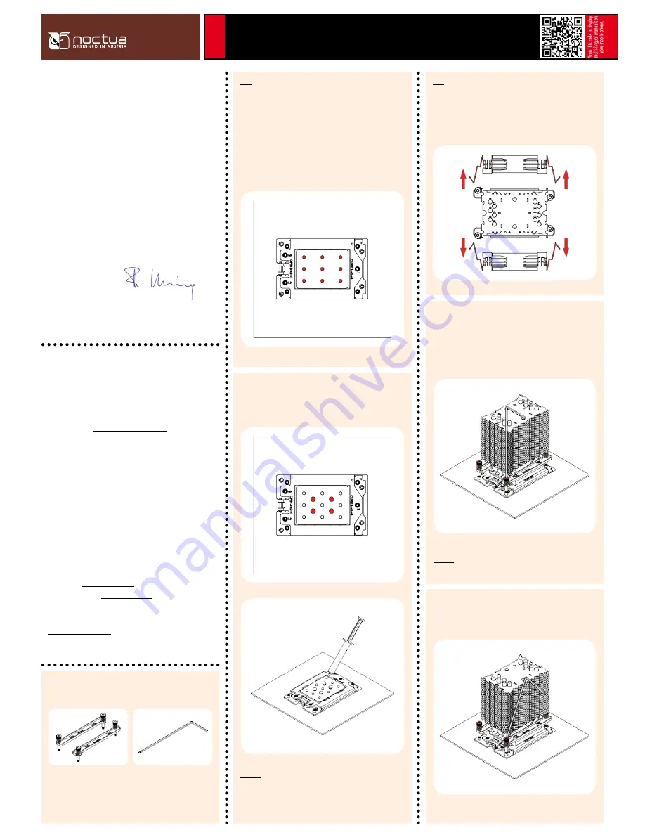
Applying thermal paste
If there are residual traces of thermal paste or thermal pads on
your CPU, please clean them off first.
Then press 9 small drops (3-4mm diameter) of NT-H1 onto the
the heatspreader in a square 3x3 pattern as shown below:
Step 1
NM-SMT3 mounting tool
NM-AFB7 fastening brackets
(pre-installed on the cooler)
Noctua NH-U9 | Installation Manual | TR4-SP3
TR4-
SP3
Caution: Applying too much thermal paste will lower heat
conductivity and cooling performance!
Continue by adding 4 larger drops (5-6mm diameter) of NT-H1 in
a square pattern at the center as shown below:
Then put the heatsink onto the CPU so that the four spring-loaded
screws align with the threads of the CPU socket. Use the sup-
plied mounting tool to tighten the screws. Perform 3 turns on each
screw, then repeat until all are fully tightened.
Caution: Gently tighten the screws until they stop, but don’t use
excessive force (max. torque 0.6 Nm).
Fastening the heatsink to the CPU
Please first take off the fans as well as the protection cover at the
bottom side of the heatsink.
Step 2
Note that you can tilt the mounting tool for reaching the screws in
case they are blocked by the heatsink fins.


