background image

7/09  FORM NO. 56043124
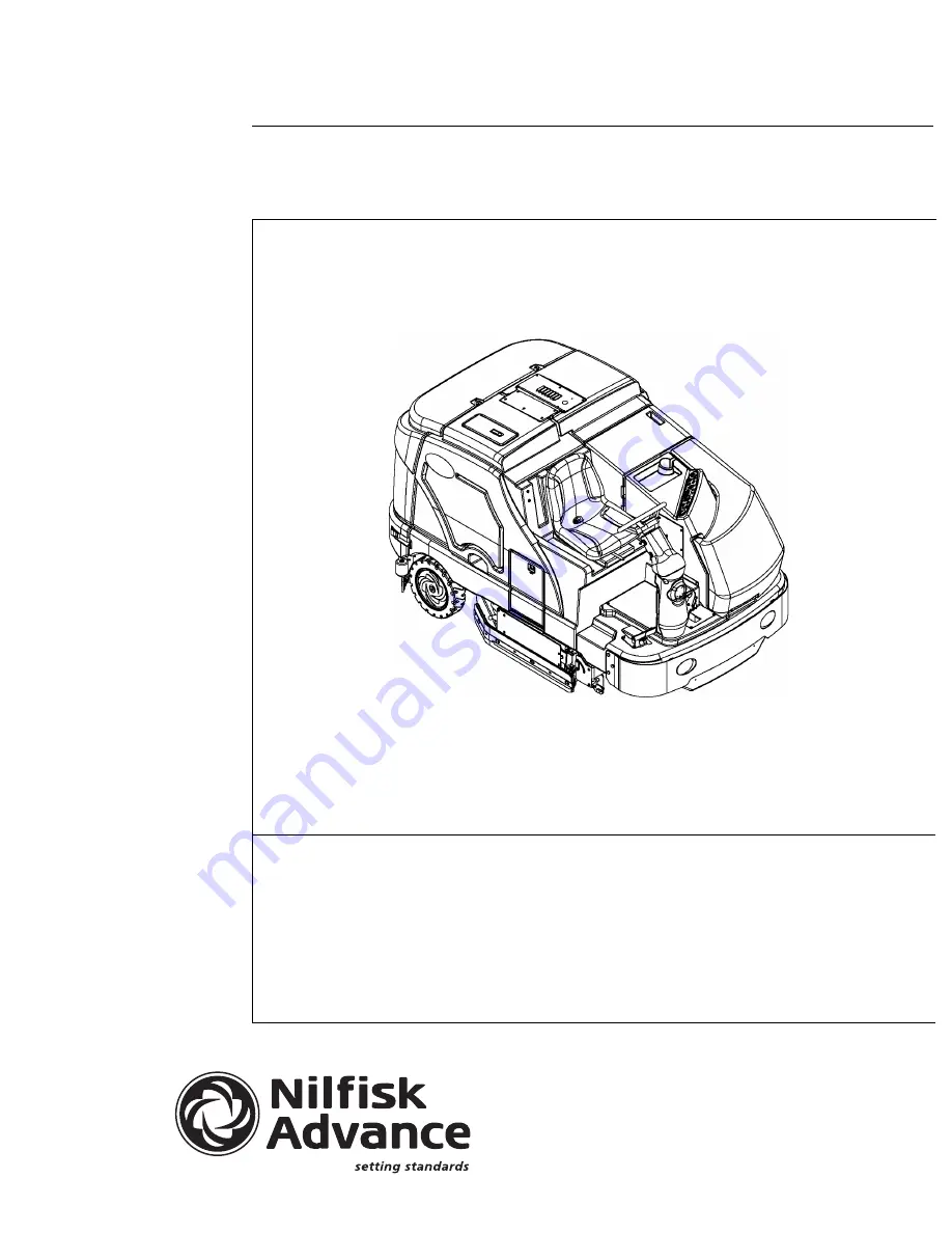
Condor XL

Service Manual

Advance Models:

56110000(LPG/48”), 56110001(Petrol/48”), 56110002(Diesel/48”), 56110003(LPG/60”), 

56110004(Petrol/60”), 56110005(Diesel/60”), 56110006(LPG/62”), 56110007(Petrol/62”), 

56110008(Diesel/62”), 56110009(LPG/67”), 56110010(Petrol/67”), 56110015(Diesel/67”)

56111035(LPG-AXP/48”), 56111036(Petrol-AXP/48”), 56111037(Diesel-AXP/48”)

56111038(LPG-AXP/60”), 56111039(Petrol-AXP/60”), 56111040(Diesel-AXP/60”)

56111041(LPG-AXP/62”), 56111042(Petrol-AXP/62”), 56111043(Diesel-AXP/62”)

56111044(LPG-AXP/67”), 56111045(Petrol-AXP/67”), 56111046(Diesel-AXP/67”)

Summary of Contents for 56110000

Page 1: ...56110006 LPG 62 56110007 Petrol 62 56110008 Diesel 62 56110009 LPG 67 56110010 Petrol 67 56110015 Diesel 67 56111035 LPG AXP 48 56111036 Petrol AXP 48 56111037 Diesel AXP 48 56111038 LPG AXP 60 56111039 Petrol AXP 60 56111040 Diesel AXP 60 56111041 LPG AXP 62 56111042 Petrol AXP 62 56111043 Diesel AXP 62 56111044 LPG AXP 67 56111045 Petrol AXP 67 56111046 Diesel AXP 67 ...

Page 2: ......

Page 3: ...TROUBLESHOOTING GUIDE TABLE OF CONTENTS 47 TROUBLESHOOTING GUIDES 48 61 CONTROL BOARD PROGRAMMING OPTIONS 62 66 ENGINE SYSTEM 67 72 ENGINE SPECIFICATIONS 67 MISCELLANEOUS ENGINE INFORMATION 68 GM 1 6L GASOLINE FUEL SYSTEM DESCRIPTION 68 ENGINE DIAGNOSTICS 69 70 1 6L DTC CODES 71 GM 1 6L ENGINE FUSE BOX WIRING 72 HYDRAULIC SYSTEM 73 83 HYDRAULIC SYSTEM COMPONENTS 73 HYDRAULIC COMPONENT LOCATION HYD...

Page 4: ...r near hydraulic system Turn the key switch 50 off O and disconnect the batteries before servicing electrical components Never work under a machine without safety blocks or stands to support the machine Do not dispense flammable cleaning agents operate the machine on or near these agents or operate in areas where flammable liquids exist Do not clean this machine with a pressure washer CAUTION This...

Page 5: ...n from the operator s position seat General Machine Description The Condor XL machines are industrial automatic rider sweeper scrubbers with multiple sweep scrub single pass coverages All models use dual cylindrical scrub brooms with variable scrub pressure and solution flow rates Different models are available with front mounted side brooms single and dual and right side disc scrub Parts and Serv...

Page 6: ...owed pushed short distances without the use of the engine See Figure 3 The tow valve is controlled by the Tow Valve Lever 34 which is accessed by opening and propping up the Engine Cover 3 Pull the Tow Valve Lever out to disengage the hydrostatic lock between the motor and pump The hydrostatic pump can be damaged if the machine is towed with the valve in the normal working position Tow Valve Lever...

Page 7: ...ist Form Number 56042484 all systems w optional kits and accessories Instructions for Use Form Number 56041705 English Spanish Engine Manuals PSI Tier II 1 6L PFI Certified Engine Service Manual G LP PSI1P6LPFI A Kubota V1505TE Diesel Engine Operator Manual English French German Italian Spanish 16622 8916 3 Kubota V1505TE Diesel Engine Service Manual English French German 97897 01640 Kubota V1505T...

Page 8: ...net access Digital voltmeter DVM with DC current clamp Hydrometer Battery load tester for checking 6V and 12V batteries Automotive fuel pressure test gauge used on gasoline engines Static control wrist strap Set of torque wrenches Hard printed copies of service manuals for regularly serviced machines available at www advance us com and other Nilfisk Advance web sites These tools are also available...

Page 9: ...043124 Condor XL 9 56305647 PSI diagnostic communication cable and software see photo PSI diagnostics cable 4 pin 8 pin Gen1 old style see photo 56504516 Hydraulic test gauge w con nector 3000 psi range see photo ...

Page 10: ...t sweep right scrub 67 in 170 cm Main brush diameter and length 11 in x 48 in 27 9 cm x 121 9 cm Side scrub brush right 16 in 40 6 cm Side broom sweep 20 in 50 8 cm Solution tank capacity 3 in from top 100 gal 378L Recovery tank shutoff 100 gal 378L Scrub brush pressure in lbs three settings 1 150 2 250 3 400 Main brush RPM 400 RPM 2200 engine RPM Debris hopper volume capacity 1 5 ft3 04 m3 Debris...

Page 11: ...FORM NO 56043124 Condor XL 11 FIGURE 4 ...

Page 12: ... lb M8 22 ft lb 13 ft lb M10 44 ft lb 25 ft lb M12 70 ft lb 40 ft lb Drive Wheel System Torque Specifications See Figure 5 Item No Description Torque Specification 1 Steering Castle Spindle Nut Torque to 40 ft lb then loosen to align cotter pin 2 16 Hex Jam Nut Torque to 150 ft lb 3 20 x 1 25 Hex Screw Use Loctite 242 torque to 90 ft lb 4 13 Nyloc Hex Nut Torque to 100 ft lb 5 Drive Wheel Motor Sp...

Page 13: ...Front wheel hydraulic cylinder and rotary valve controlled Brakes service Mechanical drum brakes one on each rear wheel cable actuated Tire front 1 drive steer Size 18 in x 6 in 457 mm x 152 mm P7 solid Tire rear 2 load bearing Size 16 in x 4 in 406 mm x 101 mm solid Solution and Chemical System Delivery Rates Solution system flow rates five settings Setting 1 1 6 gal min 6 L min Setting 2 1 9 gal...

Page 14: ...he engine oil level Check the engine coolant level in the reservoir Check for engine and coolant leaks Engine Check the air cleaner service indicator and service the air filter when the indictor is shown red Operator panel Check for a hydraulic filter plugged indicator light 66 on the operator panel display 64 Check the oil level in the hydraulic oil reservoir level should be to bottom of screen H...

Page 15: ...em EPR Maintenance Every 400 Hours Maintenance Item Procedure Air intake housing and hoses Inspect the complete air intake system for correct routing kinks restrictions sound tight connec tions holes and cracks in hoses Hydraulic hoses Inspect for leaks wear Battery Check electrolyte level check terminals for corrosion loose connections Fuel Filter Replace fuel filter cartridge located before inje...

Page 16: ...16 FORM NO 56043124 Condor XL FIGURE 6 LUBRICATION POINTS ...

Page 17: ...recommendations Refer to the engine manufacturers service manuals for oil capacities and additional engine specifications Replace the oil filter with every oil change TEMPERATURE RANGE OIL WEIGHT Above 77 F 25 C SAE 30 or 10W 30 32 F to 77 F 0 C to 25 C SAE 20 or 10W 30 Below 32 F 0 C SAE 10W or 10W 30 Diesel Lubricating Oil Note With the emission control now in effect the CF 4 and CG 4 lubricatin...

Page 18: ...r filter unless the red flag is visible in the service indicator CAUTION When servicing the engine air filter elements use extreme care to prevent loose dust from entering the engine Dust can severely damage the engine The engine air filter contains a Primary outer and a Safety inner filter element The Primary Element can be cleaned twice before being replaced The Safety Element should be replaced...

Page 19: ...ystem indicators Normally one purge cycle is adequate to purge the system Note The Detergent Box C has Detergent Level Viewing Slots D for referencing the amount of detergent remaining in the cartridge s When the detergent level is nearing the bottom of this slot refill or replace the cartridge s To Change the Detergent Mix Ratio the scrub system must be on 1 Press and hold the detergent switch 61...

Page 20: ... sweep broom s raise lower model option if equipped A B 12 Side broom s on off B L 13 Dust guard sweep dust control On Off model option if equipped A C L 14 Scrub system Raise Lower and auto scrubbing functions 15 Main scrub brushes On Off will drift 16 Scrub Brush pressure settings 1 2 3 A B 17 Solution control On Off and flow volume min max C D 18 Test purge the detergent AXP system model option...

Page 21: ...mp hydraulic filter C L 50 Gasoline Diesel fuel tank filter lines Xx hours C L W 51 LP tank hoses fittings L W 52 LP fuel filter SVR life 1500 Hrs C 53 LP fuel regulator lock off valve hoses L 54 Diesel glow plug function light hard starting 55 Gasoline Diesel fuel tank strainer yearly C 56 Brake cable and parking brake pedal A B 57 Circuit breaker panel D M W 58 Front tire check lug nut torque 10...

Page 22: ...perator s Seat 2 Solution Tank Fill Cover 3 Engine Cover 4 Recovery Tank Cover 5 Engine Air Filter Service Indicator 6 Coolant Overflow Tank 7 Engine Air Filter 8 Engine Cover Latch 9 Recovery Tank Drain Hose 10 Recovery Tank Tilt Out Latch 11 Recovery Tank Tilt Out Grip 12 Left Side Skirt Latch 13 Left Side Skirt 14 Fuel Tank petrol tank shown 15 Fuel Tank Cover Latch 16 Headlight 17 Fuel Tank Co...

Page 23: ... Skirt 32 Right Side Skirt Latch 33 Hopper 34 Tow Valve Lever 35 Battery 36 Solution Filter 37 Solution Tank Drain Hose 38 Squeegee Assembly 39 Squeegee Height Adjust Knob 40 Squeegee Mount Wrench 41 Squeegee Tilt Adjust Knob 42 Engine Oil Filter 43 Engine Cover Prop Rod 44 Hydraulic Oil Reservoir Filler Cap 45 Oil Cooler Tilt Out Latch 46 Engine Oil Dipstick 47 Right Scrub Skirt Retainer Knobs 48...

Page 24: ...tch 60 Extended Scrub Switch optional 61 Detergent System AXP models only 62 Warning Indicator Light RED see page 25 63 Left Turn Signal optional 64 Display 64a Scrub Pressure Indicator 64b Hour Meter 64c AXP Indicator optional 64d Fuel Gauge 64e Solution Flow Indicator 64f Extended Scrub Indicator optional 65 Right Turn Signal optional 66 Attention Indicator Light YELLOW see page 26 67 Emergency ...

Page 25: ... service icon Sets when the GM 1 6L engines ECM electronic control module acti vates an engine fault code See the ENGINE SYSTEM ENGINE DIAG NOSTICS section for more detailed diagnostic help 62D Battery low icon Indicates low battery voltage Check alternator output test the battery clean and tighten cables 62E Controller critical fault icon The main control board has sensed a specific system compon...

Page 26: ...d the glow plugs are activated heating up for their timed 10 seconds The engine can be cranked to start when the yellow attention light and display icon go out 66E Recovery tank full icon The tank float has sensed a high water level The operator needs to empty the waste water from the tank If tank is empty and icon is dis played service clean the tank float could be stuck Also check the float circ...

Page 27: ...11 Squeegee UP solenoid L3 over current x x x x 12 Squeegee DN solenoid L2 over current x x x x 13 Scrub motor solenoid L4 over current x x x 14 Glow plug relay K4 coil over current 15 Scrub cylinder lock solenoid L6 over current x x x 16 RT side scrub sweep motor solenoid L8 over current x x 17 Back Up alarm over current 18 RT side scrub lift cylinder solenoid L9 over current x 19 Horn over curre...

Page 28: ... and side sweep RT scrub electrical ladder detail 15 C Scrub cylinder lock solenoid over current Check L6 solenoid coil wiring for problems ORN and YEL BLU Check coil resistance less than 6 ohms replace Also see main scrub on and RT scrub brushes deck pressure electrical ladder detail 01 C Scrub brush pressure valve solenoids over current Check L5 down and L7 up pressure valve solenoid coils on sa...

Page 29: ...olenoid valve over current Check L8 solenoid coil wiring for problems ORN and BLK WHT Check coil resistance less than 6 ohms replace Also see main scrub on and side sweep right scrub electrical ladder detail Side Mist System Code Fault Description by System Family Troubleshooting Actions and Comments 04 NC Side sweep mist pump over current Check Pump motor M5 wiring for problems BLU and YEL BLK Te...

Page 30: ... breaker CB3 over current Control board has sensed open circuit fault for CB3 power for side broom actuator motor M7 Check for Violet wire shorted to ground 28 C 20A Circuit breaker CB4 over current Control board has sensed open circuit fault for CB4 power for hydrau lic solenoid manifold coils L4 L 11 Check for Orange wire shorted to ground 29 C 10A Circuit breaker CB5 over current Control board ...

Page 31: ...temperature too high diesel oil pressure low diesel or engine run has change to ignition inhibit and key is on gas and pro pane Note Engines will shut down See engine section for the list of engine codes and process for reading extracting codes 36 NC Service engine fault Gasoline LP engine GM 1 6 only sets when ECM activates MIL output could be for mf any different reasons See engine section for t...

Page 32: ...NT LOCATIONS GM 1 6 GASOLINE O2 Sensor in exhaust manifold pre CATCON TMAP Sensor ETC Electronic Throttle Control ECT Engine Coolant Temperature Sensor Fuel Injectors and Connectors Fuel Pump and Manifold mounted on fuel tank ECM and Oil Pressure Switch Crank Position Sensor ...

Page 33: ...MPONENT LOCATIONS GM 1 6 LPG Fuel Temperature Sensor mounted on EPR LPG only TMAP Sensor ETC Electronic Throttle Control O2 Sensor in exhaust manifold ECT Engine Coolant Temperature Sensor EPR and Fuel Lockout and Filter ECM and Oil Pressure Switch Crank Position Sensor ...

Page 34: ...L ELECTRICAL SYSTEM ENGINE ELECTRICAL COMPONENT LOCATIONS KUBOTA DIESEL Oil Pressure Sensor above oil filter Coolant Temperature Sensor above alternator Governor Engine Speed Magnetic Pickup Woodward Governor and Throttle Actuator ...

Page 35: ...FORM NO 56043124 Condor XL 35 ELECTRICAL SYSTEM ELECTRICAL COMPONENT LOCATIONS Extended Scrub Pump Extended Scrub Float Switch Recovery Tank Full Switch Drive Pedal Sensor ...

Page 36: ...36 FORM NO 56043124 Condor XL ELECTRICAL SYSTEM ELECTRICAL COMPONENT LOCATIONS Mist Pump if so equipped Solution Pump top and Wash Pump bottom AXP Pumps behind cover panel ...

Page 37: ...FORM NO 56043124 Condor XL 37 ELECTRICAL SYSTEM CONTROL BOARD ASSEMBLY J3 J2 J1 Board Relay Start Run Inhibit K1 Power Relay ...

Page 38: ...un J1 13 Open J1 14 Open J1 15 Open J1 16 18 1 RED BLK input S29 Horn switch J1 17 Open J1 18 16 1 BLK ground Chassis ground X 49 J1 19 18 1 GRN ORN input Sender hydraulic oil temperature J1 20 18 1 VIO WHT input S6 Brake switch J1 21 18 1 VIO YEL input S3 Solution empty switch J1 22 18 1 WHT BRN output Relay PCB start inhibit pin J7 3 J1 23 Open J1 24 18 2 VIO BRN input Ignition switch start posi...

Page 39: ...nput CB4 circuit breaker 20A J2 13 18 1 WHT ORN output K4 glow plug relay coil J2 14 Open J2 15 Open J2 16 Open J2 17 16 2 BLK input X49 control box ground J2 18 16 3 BLK input X49 control box ground J2 19 Open J2 20 Open J2 21 Open J2 22 18 1 YEL GRN output L10 solenoid valve main solution J2 23 18 3 GRN BRN input CB5 circuit breaker 10A J2 24 18 1 ORN RED output S7 scrub pressure proportional so...

Page 40: ...s and taillights J3 9 16 1 GRA RED input CB1 Circuit Breaker 20A J3 10 Open J3 11 16 4 BLK input X49 control box ground J3 12 16 5 BLK input X49 control box ground J3 13 16 6 BLK input X49 control box ground J3 14 16 3 BLU input CB2 Circuit Breaker 20A J3 15 16 2 BLU input CB2 Circuit Breaker 20A J3 16 18 1 VIO input CB3 Circuit Breaker 15A J3 17 18 1 WHT YEL output horn J3 18 16 1 YEL BLK output ...

Page 41: ...ts Out limit 8 Measure the position of the drive nut on the actuator shaft and compare the measurement with the OUT position shown in Figure 7 9 If the measurement doesn t match the dimension shown it will be necessary to remove the large rubber Adjuster Cover AF Note Use a 1 2 13mm socket to turn the outside hex adjuster Each click of the top adjuster cam will change the nut travel 1 16 1 6mm To ...

Page 42: ...e Piston Pump Lever Weldment E returns the pedal and Piston Pump G to the neutral position when the pedal is released A rotary potentiometer called the Rotary Sensor F is attached to the Piston Pump and the resistance through the Rotary Sensor will vary with the position of the Piston Pump Lever Weldment When the engine is started the Control Board Driver Box checks the Rotary Sensor resistance to...

Page 43: ...9 Loosen the jam nut and turn the Adjustment Screw B clockwise or counterclockwise to move the Adjuster Plate and Hydroback unit D as required to stop any wheel movement The Piston Pump Lever Weldment E on the Piston Pump G is now in the neutral position 8 Tighten the two 5 16 18 hex head screws to secure the Adjuster Plate to the chassis 9 Tighten the jam nut on the Adjustment Screw 10 Test the n...

Page 44: ...ld Cable routing path in the machine This will eliminate a lot of disassembly and reassembly work 13 Once the new Push Pull Control Cable has been threaded through the machine disconnect it from the old Cable 14 Reinstall the two jam nuts and star washer onto the pedal end of the Push Pull Control Cable Position the jam nuts and star washer in the same location as noted in step 5 above 15 Remove t...

Page 45: ...otary Sensor or Control Board you will have to recalibrate the neutral deadband position and set the sensitivity 1 Depress the foot pedal to full reverse position then allow the pedal to slowly return to its neutral position Do not move the pedal during the remainder of this procedure 2 Press and hold the Engine Speed Switch 51 then turn the ignition Key Switch 50 to the run on position Continue t...

Page 46: ...he Hydraulic Hoses to the motor are replaced or repaired it s important to route the Hoses correctly when reinstalled to prevent wear or damage to the Hoses and surrounding components When reinstalling the traction drive motor Hydraulic Hoses 1 Tighten the hoses at the bulkhead fittings on the frame 2 Turn the steering wheel all the way toward the left 3 Make sure the Hoses are routed up and insid...

Page 47: ...T RUN RELAY GM 50 ENGINE START RUN RELAY KUBOTA 51 ENGINE SPEED MAGNETIC PICKUP WOODWARD GOVERNOR 52 MAIN SCRUB DECK RIGHT SCRUB DOWN 53 MAIN SCRUB AND SIDE SWEEP SCRUB ON 54 VACUUM FAN ON AND SQUEEGEE DOWN 55 VACUUM FAN OFF AND SQUEEGEE UP 56 MAIN AND RIGHT SIDE SCRUB BRUSH SOLUTION VALVES AND PUMP 57 MAIN AND RIGHT SIDE SCRUB BRUSH ES DECK PRESSURE 58 AXP PCB ASSEMBLY 59 ...

Page 48: ...ON Conditions S1 Key turned on S1 POWER RELAY KEY SWITCH PIN J2 1 K1 RELAY COIL F1 FUSE 100A BAT K1 B SUPPLY CB1 CB2 CB3 CB4 CB5 B OUTPUT IGN RUN ON 12V DC BATTERY CB6 15A BLU GRN ORN GRN VIO GRA RED RED VIO DRIVER BOX Component Current Amps Coil Ohms K1 Relay Coil 29 Amps 12V 46 5 ohms ...

Page 49: ... its needed input switch command This prevents the ignition system from firing and if the engine is running will cause it to shut down Important See the list for possible reasons the inhibit functions start and run could be active or inhibited Possible causes for start inhibit to be active causing the engine not to crank Drive pedal sensor switch R1 not calibrated follow programming instructions t...

Page 50: ...n Neutral DRIVE BOX PIN J1 22 PIN J1 34 PIN J1 10 PIN J1 31 PIN J1 11 Battery From F1 Fuse 100A CB6 15A S1 K2 K3 R1 START B1 IGN J7 6 J7 3 J7 7 J7 8 START INHIBIT RUN INHIBIT J7 4 J7 2 J7 5 K2 K3 DRIVE PEDAL SENSOR BAT BAT 3 J7 1 RELAY PCB START COM MAND TO STARTER RELAY IGN SW INPUT ALT EXCITE 1 2 3 Note See connector callout page for engine run start relay module for more details on circuit func...

Page 51: ...TART STARTER BLU PINK ALTERNATOR G2 GOVERNOR A5 M3 B PINK RED ELECTRICAL SYSTEM TROUBLESHOOTING GUIDE ENGINE START RUN RELAY KUBOTA DIESEL Conditions First turn the key S1 to the run position the glow plug icon will appear on the operator display panel Next wait until the glow icon goes out then turn the key to the start position and release to the run position Foot pedal in Neutral Note See conne...

Page 52: ...additional trouble shooting notes for control circuit details SPEED 1 2400 RED B B S1 TO ENGINE FLYWHEEL MAGNETIC PICKUP 12V Engine Run Signal RELAY PCB PIN J7 1 PIN J7 5 Mounts to Engine Injector Pump FUEL RAIL SHUT DOWN ACTUATOR SPEED 2 2200 DIAGNOSTIC SERVICE TOOL CONNECTOR VIO GRA S28 WOODWARD GOVERNOR Run Relay Out J7 5 Ref Engine Start Run Relay for more detail OIL PRESSURE SWITCH SHOWN IN L...

Page 53: ...adder diagram for speed selection voltage relationships If 0 volts check continuity of speed select input wiring from governor to the main controller If wiring check is ok substitute a new main controller driver box dash board panel Check status lamp on governor for fault codes reference flash code table found on APECS 3000 website Test governor controller actuator out put voltage at different spe...

Page 54: ...rub ON mode selected Component Current Amps Coil Ohms L5 2 1 Amps 2 2 ohms L6 1 5 Amps 8 ohms L9 1 5 Amps 8 ohms 12VDC 12VDC 0V L6 B B from K1 Power Relay 12V DC B OUTPUT TOUCH PAD DASHBOARD PANEL CB4 20A ORN B B RED VIO DRIVER BOX PIN J2 26 MAIN SCRUB LIFT CYLINDER DOWN WHT VIO SCRUB CYLINDER LOCK PIN J2 4 YEL BLU B OUTPUT L5 S1 KEY SWITCH B1 L9 ...

Page 55: ...ng Scrub ON mode selected Foot pedal activated out of neutral Component Current Amps Coil Ohms L4 1 5 Amps 8 ohms L8 1 5 Amps 8 ohms 12VDC 12VDC PIN J2 7 L4 B B from K1 Power Relay B OUTPUT TOUCH PAD DASHBOARD PANEL CB4 20A BLK WHT ORN PIN J2 2 B OUTPUT L8 SIDE SWEEP RIGHT SCRUB ORN BLU B B DRIVER BOX MAIN SCRUB BRUSH S1 KEY SWITCH B1 ...

Page 56: ...ode selected or vacuum switch selected Foot Pedal activated out of neutral Component Current Amps Coil Ohms L1 1 5 Amps 8 ohms L2 1 5 Amps 8 ohms PIN J2 5 L2 SQUEEGEE DOWN B B from K1 Power Relay B OUTPUT TOUCH PAD DASHBOARD PANEL BRN YEL PIN J2 8 B OUTPUT L1 VACUUM FAN SOLENOID RED GRA B CB5 10A GRN BRN B DRIVER BOX S1 KEY SWITCH B1 12VDC 12VDC ...

Page 57: ... Mode selected or vacuum switch turned off Foot Pedal placed in reverse squeegee will raise up Component Current Amps Coil Ohms L3 1 5 Amps 8 ohms L2 B B from K1 Power Relay B OUTPUT TOUCH PAD DASHBOARD PANEL L1 B CB5 10A GRN BRN B RED VIO DRIVER BOX PIN J2 6 L3 SQUEEGEE UP SOLENOID BRN GRN SQUEEGEE DOWN VACUUM FAN S1 KEY SWITCH B1 12VDC 0V 0V ...

Page 58: ...rward direction Component Current Amps Coil Ohms L10 1 5 Amps 8 ohms L11 1 0 Amps 12 ohms M4 11 5 Amps FLA FLA Full Load Amps L10 B B from K1 Power Relay B OUTPUT TOUCH PAD DASHBOARD PANEL CB4 20A ORN L11 B CB5 10A GRN BRN B RED VIO RED VIO DRIVER BOX PIN J3 2 M4 MAIN SOLUTION PUMP GRN BLU MAIN SOLUTION VALVE RIGHT SIDE SOLUTION VALVE PIN J2 22 PIN J2 10 YEL GRN BLU YEL B OUTPUT B OUTPUT S1 KEY SW...

Page 59: ...PWM 12VDC Variable 12VDC PWM ELECTRICAL SYSTEM TROUBLESHOOTING GUIDE MAIN and RIGHT SIDE SCRUB BRUSH ES DECK PRESSURE Conditions Key ON Engine running Scrub System ON Foot pedal activated out of neutral Component Current Amps Coil Ohms L5 2 1 Amps 2 2 ohms L6 1 5 Amps 8 ohms L7 2 1 Amps 2 2 ohms Pressure Setting L5 Coil Amp draw readings 10 1 1 38 1 75 amps varies with scrub setting selected 2 3 P...

Page 60: ... good but no current is found when activating scrub deck pressure circuit function If electrical control circuits test OK see possible causes for the Hydraulic load circuit problems Hydraulic load circuit Inspect for binding and any possible mechanical damage to the deck lift cylinder and deck lift linkage Remove the S5 S7 scrub lift cylinder valve cartridges from its manifold Inspect clean and op...

Page 61: ...e main controller Driver Box is probably defective Check the resistance of the chemical pump before replacing the main controller Driver Box so as not to damage it if the pump is defective The Solution Pump line provides a switched ground return for the pump When the solution pump is ON a 7 8KHz signal with a varying duty cycle and average voltage will appear between this pin and B Measuring with ...

Page 62: ...t it s normal for this value to drift a little 4 Press the green Scrub ON Switch to set the nominal deadband resistance value The display will return to the previous menu 5 Press the Side Broom Down Switch 53a to move the arrow to the left of the Neutral Deadband line 6 Press the green Scrub ON Switch to display the Neutral Deadband range menu The percentages shown are the limits the resistance fr...

Page 63: ...s menu level 6 To exit the Configuration Display turn the ignition Key Switch to the off position ENGINE TYPE CONFIGURATION DISPLAY UNDEFINED PROPANE GASOLINE DIESEL SIDE SCRUB SYSTEM NOT INSTA LLED INSTA LLED SIDE SWEEP SYSTEM NOT INSTA LLED INSTA LLED EXTENDED SCRUB SYSTEM NOT INSTALLED INSTALLED BACK UP ALARM NOT INSTA LLED INSTA LLED LIGHTS NOT INSTA LLED INSTA LLED DETERGENT SYSTEM NOT INSTA ...

Page 64: ...ECON DS 0 3 SEC INCREMENT 0 5 SEC 0 1 2 3 4 5 6 7 8 9 LAST USED 1 2 3 4 5 1 2 3 OFF ON LAST STAT E 1 2 3 MODE 1 LAST USED 1 2 3 1 2 3 1 2 3 4 5 1 2 3 4 5 0 1 2 3 4 5 6 7 8 9 LAST USED 0 1 2 3 4 5 6 7 8 9 LAST USED SOLUTION FLOW START LAST USED 1 2 3 4 5 AUTOMATIC MANUAL SCRUB_RESUME_LAST_FLG 0 scrub mode 1 1 last used LAST_SCRUB_MODE 1 2 OR 3 CHEMICAL_START_MODE 0 off 1 on 2 last state SCRUB_FUNCT...

Page 65: ...UUM_OFF_DELAY 100 300 default 100 RECOVERY_TIMEOUT_MODE 0 normal 1 in neutral CONTROL_LOCK 0 unlock 1 detergent mix only 2 detergent mix and solution flow Only appears when SIDE_SCRUB_INSTALLED_FLG 1 from configuration menu SIDE_SCRUB_START_MODE 0 off 1 on 2 last state Only appears when SIDE_SWEEP_INSTALLED_FLG 1 from configuration menu SIDE_SWEEP_START_MODE 0 off 1 on 2 last state SIDE_MIST_START...

Page 66: ... the previous menu level without selecting the option 8 To save the new setting s turn the ignition Key Switch to the off position The new setting s will be saved and remain in effect until changed again ENGINE TYPE CONFIGURATION MENU UNDEFINED PROPANE GASOLINE DIESEL SIDE SCRUB SYSTEM NOT INSTALLED INSTALLED SIDE SWEEP SYSTEM NOT INSTALLED INSTALLED EXTENDED SCRUB SYSTEM NOT INSTALLED INSTALLED B...

Page 67: ...CM Engine Rotation CCW flywheel end Valve lifters Hydraulic Oil Capacity 3 7 qt 3 5L with Oil Filter Oil Pressure 21 psi minimum with engine hot at idle Cooling System 3 5 qt Engine Only Kubota V1505 B 1 Engine Type Vertical liquid cooled 4 cylinder 4 cycle diesel engine Displacement 91 41 cubic inches 1498cc Fuel Diesel fuel No 2 D ASTM D975 Injection Pump Bosch MD type mini pump Engine firing or...

Page 68: ...L GASOLINE FUEL SYSTEM DESCRIPTION This engine is equipped with a fuel injector rail that does not have a pressure regulator Fuel pressure for this engine is regulated by the engine s ECM controlling the fuel pump via pulse width modulation The ECM receives fuel pressure and temperature feedback from the gasoline fuel sen sor manifold and uses this information to control the ground side of the fue...

Page 69: ...iagnostic information To use the Controller Interface Kit 1 Install the software from the provided CD onto your PC 2 Connect the USB connector on the kit cable to a USB port in your PC 3 See Figure 13 Remove the Protective Cap then connect the kit cable to the Communication Port on the engine Note The minimum system requirements for the software in the Controller Interface Kit are as follows Windo...

Page 70: ... error code 118 indicating an ECT engine coolant temperature High Voltage condition would be indicated as follows a The light will show one blink a short pause six blinks a short pause five blinks a short pause then one blink Note that this 1 6 5 4 sequence is not an error code but will repeated three times to indicate the beginning of the error code number display series b The light will show the...

Page 71: ...P Low Pressure 108 1 1165 LPG Cat Monitor 520213 10 134 EGO 1 Open Inactive 724 10 1171 LPG Pressure Higher Than Expected 520260 0 154 EGO 2 Open Inactive 520208 10 1172 LPG Pressure Lower Than Expected 520260 1 171 Adaptive Learn High Gasoline 520200 0 1173 EPR Comm Lost 520260 31 172 Adaptive Learn Low Gasoline 520200 1 1174 EPR Voltage Supply High 520260 3 182 Fuel Temp Gasoline Low Voltage 174...

Page 72: ...72 FORM NO 56043124 Condor XL ENGINE SYSTEM ...

Page 73: ...der Ass y 54 Hydraulic Motor Ass y 55 Drive Motor Ass y 56 Pump Assembly Low Speed 57 Valve Block Ass y 58 Cylinder Assembly Steer 59 Scrub Lift Cyl Ass y 60 Oil Cooler Ass y Item Description 62 Pump Assembly 63 Union Cross 64 End Cap Flare Tube 65 Locknut Bulkhead 66 Locknut Bulkhead 68 Sleeve Nylon 69 Clamp P 70 Elbow 90 Bulkhead Union 71 Nipple Test 72 TEE BULKHEAD RUN ...

Page 74: ...FORM NO 56043124 Condor XL HYDRAULIC SYSTEM HYDRAULIC CYLINDERS Item Ref No Qty Description A 56110261 1 Squeegee Cylinder Ass y B 56110412 1 Cylinder Assembly Steer C 56110425 1 Scrub Lift Cylinder Ass y ...

Page 75: ...ndor XL 75 HYDRAULIC SYSTEM HYDRAULIC MOTORS Item Ref No Qty Description A 56110062 1 Vacuum Fan Motor Assembly B 56111517 1 Steering Pump Assembly C 56110369 1 Drive Motor Assembly D 56110339 1 Main Broom Motor Assembly ...

Page 76: ...76 FORM NO 56043124 Condor XL HYDRAULIC SYSTEM HYDRAULIC PUMPS Item Ref No Qty Description A 56111085 1 Propulsion transport Pump Assembly B 56110372 1 Accessory Pump Assembly ...

Page 77: ...PD222 The most con venient way to check for oil flow is to check the RPM of the motor that is performing poorly Refer to the GENERAL HYDRAULIC SPECIFICATIONS TABLE to determine the motor RPM If the motor speed is correct the pump is producing the correct amount of oil flow However this does not mean that if a motor is running too slow the problem is in the pump The following information should be ...

Page 78: ...inders will operate A much lower than normal bypass pressure could indicate a gear pump problem If the bypass pressure remains the same after turning the function on there could be a problem in the control valve or circuit If the operational pressure is within range but the motor speed is too slow the problem could be in the motor If the broom motor operational PSI reading is above the bypass psi ...

Page 79: ...ry Pump 2b Circuits Displacement Cu In GPM RPM IN RPM OUT PSI Relief PSI Accessory Pump 2b priority branch engine 2200 RPM no systems running test port TP3 1 20 3 0 2200 296 1500 Steering unit driving and turning 4 5 500 Test Port Pressure Type Controlled by Pressure Setting PSI 1 750 774 2 750 767 TP4 Lift Pressure Proportioning Valve S7 3 745 779 1 333 346 2 393 412 Scrub lift cylinder 1 50 x 5 ...

Page 80: ...ift cylinder This combination of up and down forces on the lift cylinder applies the correct amount of downward force to the main scrub deck to produce the desired scrub pressure Note that the signals to the valves allow the valves to dither oscillate in a slight back and forth motion high frequency to prevent the valves from sticking The table below shows the hydraulic pressures to the Valves and...

Page 81: ...lve cartridges are the same the S2 and S3 valve cartridges are the same and can be swapped for troubleshoot ing purposes D The S5 S6 S7 S8 and S9 valve cartridges are all different and only one of each is used Item Component Description and Hydraulic Circuit Function LI S1 Solenoid coil and valve cartridge vacuum fan motor coil 8 ohms L2 S2 Solenoid coil and valve cartridge squeegee lift cylinder ...

Page 82: ...82 FORM NO 56043124 Condor XL HYDRAULIC SYSTEM ...

Page 83: ...FORM NO 56043124 Condor XL 83 HYDRAULIC SYSTEM ...

Page 84: ...al resolution is required J1 10 5V output Throttle Position 3 3V A 3 3v A 3 3V B Pedal Position Potentiometer End 5K ohm Drive pedal sensor High side J1 11 Ground Output Throttle Position Ground Ground 0V B Pedal Position Potentiometer End 5K ohm Drive pedal sensor Low side J1 12 Input Ignition Input Volt age Analog Volt age B B System Volt age From key switch Ignition position J1 16 Input Horn Sw...

Page 85: ...k is empty J1 34 Output Ignition Inhibit Low Side Driver 0V B MOSFET Gate On Relay PCB Assy 3 Ma 12V Ground or float J2 1 Output Main Power Relay Low Side Driver 0V B Relay Coil 0 29A 12V 46 5 ohms J2 2 Output Side Sweep Scrub Solenoid Low Side Driver 0V B Hydraulic Coil 1 5A 12V 8 ohms 20 C J2 3 Output Side Scrub Lift Sole noid Low Side Driver 0V B Hydraulic Coil 1 5A 12V 8 ohms 20 C J2 4 Output ...

Page 86: ...2V B Engine Control Module Input 12V for 2400 RPM float other wise J2 30 Output ECM En gine 2400 RPM High Side Driver 12V B Engine Control Module Input 12V for 2200 RPM float other wise J2 31 Output Left Front Turn Lamp High Side Driver 12V B Incandescent Lamp 0 33A 12V 0 4A 14 5V 4W turn lamp J2 32 Output Right Front Turn Lamp High Side Driver 12V B Incandescent Lamp 0 33A 12V 0 4A 14 5V 4W turn ...

Page 87: ...d 0V B Ground J3 14 Power B Circuit Breaker2 VACC2 Power 12 15VDC B System Volt age Power from circuit breaker 2 20A J3 15 Power B Circuit Breaker 2 VACC2 Power 12 15VDC B System Volt age Power from circuit breaker 2 20A J3 16 Power B Circuit Breaker 3 VACC3 Power 12 15VDC B System Volt age Power from circuit breaker 3 15A J3 17 Output Horn Low Side Driver 0V B Electromag netic Horn 4A 12V J3 18 O...

Page 88: ...g are set x x 04 SIDE_MIST_PUMP_FAULT_FLG FAULT_SIDE_SWEEP_MIST_PUMP x x RECYCLE_SYSTEM_FAULT_FLG set if any of the following are set x x 00 SOLUTION_PUMP_FAULT_FLG FAULT_SOLUTION_PUMP same fault line used for clean and recycle pumps x ENGINE_SPEED_FAULT_FLG set if any of the following are set x x 05 2200RPM_OUT_FAULT_FLG FAULT_ECM_2200 x x 06 2400RPM_OUT_FAULT_FLG FAULT_ECM_2400 x x 10 RECYCLE_SO...

Page 89: ...Tank 2 Solution Flow Control Valve 3 Solution Filter 4 Main Solution Pump M4 5 Main Solution Valve L10 6 Right Solution Valve L11 7 Solution Tank Drain Hose Only if equipped with Right Front Scrub APPENDIX SOLUTION FLOW DIAGRAM STANDARD WITH RIGHT FRONT SCRUB ...

Page 90: ...3 Solution Filter 4 Main Solution Pump M4 7 Solution Tank Drain Hose 8 Mist Pump M5 9 Wand Pump M8 10 Mist Spray Nozzles 11 Wash Hose Spray Gun A Solution flow to the scrub deck see Solution Flow Diagram Standard with Right Front Scrub for more details SOLUTION FLOW DIAGRAM ACCESSORIES APPENDIX ...

Page 91: ...on Filter 4 Main Solution Pump M4 5 Main Solution Valve L10 7 Solution Tank Drain Hose 12 Reducer Tee 13 Y Barb Fitting 14 Detergent Pumps M10 M11 15 Detergent Tank B Location for the Right Front Scrub Tee if equipped C Location for the Extended Scrub Tee if equipped APPENDIX SOLUTION FLOW DIAGRAM AXP ...

Page 92: ...M4 5 Main Solution Valve L10 7 Solution Tank Drain Hose 16 Extended Scrub Pump M6 17 Solution Coupler Quick Disconnect 18 Strainer 19 Float Switch 20 Float Wiring Quick Disconnect 21 Recovery Tank B Location for the Right Front Scrub Tee if equipped D Location for the AXP Tee if equipped SOLUTION FLOW DIAGRAM EXTENDED SCRUB APPENDIX ...

Page 93: ...FORM NO 56043124 Condor XL 93 APPENDIX HYDRAULIC SCHEMATIC ...

Page 94: ...6 3 CAN J6 4 CAN J6 1 B J6 2 B IGNITION INHIBIT J3 1 J3 9 J1 19 J1 18 J2 17 J2 18 J3 11 J3 12 J3 13 J1 1 RUN SIGNAL GROUND FUEL PUMP CLOSES WHEN TANK IS EMPTY CLOSES WHEN TANK IS EMPTY NOTE S5 IS USED ON LPG ONLY J3 4 M7 ACTUATOR MOTOR WIRING WHITE RED CW EXTEND WHITE BLACK CCW RETRACT WHITE COMMON J1 31 J3 5 J3 7 J1 10 J1 11 J2 34 J2 33 J2 32 J2 31 J3 8 J7 6 J7 3 IGNITION_KEYPOS J1 12 J7 8 J7 5 J...

Page 95: ...113 B X1 X1 A E1 E1 1 2 M M4 PUMP SOLUTION M M4 PUMP SOLUTION X113 X113 C LP4 LAMP LEFT REAR S T T LP4 LAMP LEFT REAR S T T BLK RED WHT D2 DIODE D2 DIODE M M6 PUMP EXT SCRUB OPTIONAL M M6 PUMP EXT SCRUB OPTIONAL M M11 PUMP CHEMICAL 2 M M11 PUMP CHEMICAL 2 L10 VALVE MAIN SOLUTION L10 VALVE MAIN SOLUTION 1 2 L1 VAC FAN S1 L1 VAC FAN S1 1 2 H3 BACK UP ALARM OPTIONAL H3 BACK UP ALARM OPTIONAL 1 2 CB4 ...

Page 96: ... B B A B SP16 SP16 1 2 S29 SWITCH PUSH BUTTON HORN S29 SWITCH PUSH BUTTON HORN 1 2 X15 X15 1 2 A B A B X2 X2 A B C D E F G H J K L M N P R S LP6 LAMP RIGHT FRONT TURN LP6 LAMP RIGHT FRONT TURN WHT BLK CB5 CIR BREAKER 10 AMP VACC5 CB5 CIR BREAKER 10 AMP VACC5 1 2 M M7 ACTUATOR SIDE BROOM M M7 ACTUATOR SIDE BROOM BLK RED WHT CB3 CIR BREAKER 15 AMP VACC3 CB3 CIR BREAKER 15 AMP VACC3 1 2 GROUND CONTRO...

Page 97: ...U PINK 16 1 PINK YEL 16 1 BLK RED 16 1 PINK 16 8 PINK 16 7 GRA BLU 18 1 GRA 18 1 VIO BLU 18 1 GRN RED 8 1 BLK YEL 18 1 ORN BLK 18 1 GRA ORN 18 1 THROTTLE INPUT 12V FOR 2200 RPM B GRA ORN 18 1 SPEED SELECT 1 2400 RPM SPEED SELECT 2 2200 RPM B B B B X1_ X1_ A B C D E F G H J K L M N P R S M13 STARTER M13 STARTER 30 50 D3 D3 E4 E4 1 2 X2_ X2_ A B C D E F G H J K L M N P R S SP28 SP28 1 2 2 X2 X2 A B ...

Page 98: ...JECTOR 4 FUEL PUMP RELAY FUEL PUMP BATT GROUND ALTERNATOR ALTERNATOR ALTERNATOR DIAGNOSTIC CONNECTOR CONNECTOR 1 VEHICLE INTERFACE CONNECTORS CONNECTOR 2 B L H J I E D F G A K C EGO 2 EGO 1 ECT BOSCH_TMAP OIL PRESSURE SENSOR IGNITION COIL CRANK SENSOR GROUND POWERRELAY IGNITION STARTER RELAY STARTER SOLENOID ECM STARTER VSW GCP 90 WAY CONNECTOR Q ...

Page 99: ...Y CONNECTOR BOSCH THROTTLE BATT GROUND ALTERNATOR ALTERNATOR ALTERNATOR DIAGNOSTIC CONNECTOR CONNECTOR 1 VEHICLE INTERFACE CONNECTORS CONNECTOR 2 N L H J I E D F G A K C EGO 2 EGO 1 ECT BOSCH_TMAP OIL PRESSURE SENSOR IGNITION COIL CRANK SENSOR GROUND EPR IGNITION STARTER RELAY STARTER SOLENOID ECM STARTER VSW M LOCKOFF P ...

Page 100: ...9 VIO BLU J1 30 GRA J1 1 S R P N M L K J H G COOLANT TEMP OUTPUT F E D RUN SIGNAL GROUND C B A X2 WHT GRN 18 1 GRN RED 18 1 GRN WHT 18 1 BLK GRN 18 1 D C B A X78 GASOLINE MODELS ONLY DIAGNOSTIC CONNECTOR Machine Harness Connectors ECM Harness Connectors WHITE LT GREEN 18 LT GREEN RED 18 LT GREEN WHITE 18 BLACK LT GREEN 18 D C B A Wiring Harness Wiring Harness Component Description Item A ECM Wirin...

Page 101: ...LER PROGRAMMING OPTIONS Programming Option Switches Pressed to Access Option Foot Pedal Neutral Deadband Engine Speed 51 Configuration Display Emergency Flashers 67 User Options Menu Scrub OFF Switch 55 Scrub ON Switch 54 Configuration Menu Emergency Flashers 67 Headlight 68 ...

Page 102: ......

Reviews: