background image

in

fo

@

n

if

ty

li

ft

.c

o

m

.com

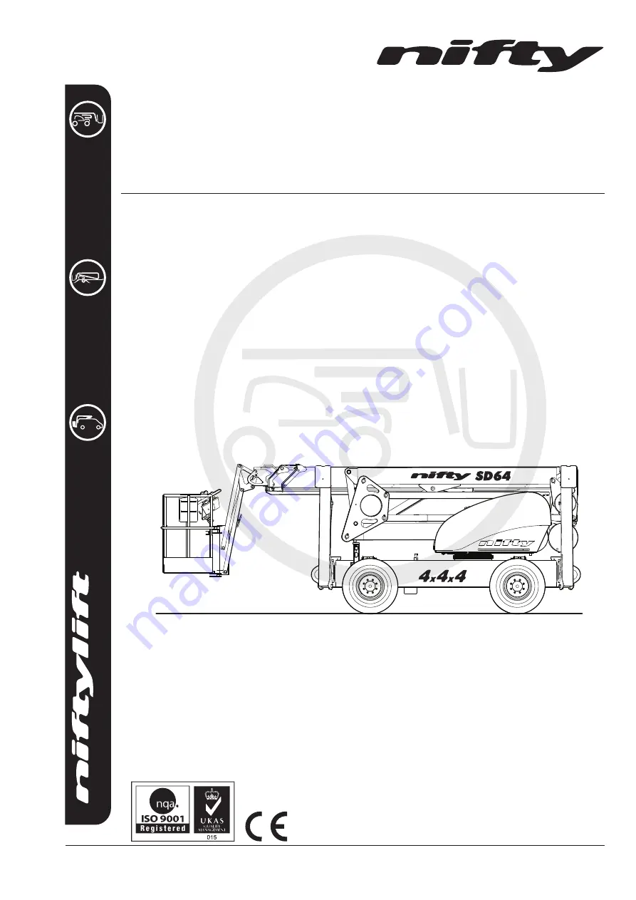
SD64

Operating & Safety Instructions

MODEL SD64 SERIES

SCALE

1.000

M50407/0

4

Niftylift Limited

www.niftylift.com

e-mail: [email protected]

Tel: 864-968-8881

Fax: 864-968-8836 

1525 S. Buncombe Road

Greer

SC 29651

USA

Summary of Contents for SD64 4x4x4

Page 1: ...c o m com SD64 Operating Safety Instructions MODEL SD64 SERIES SCALE 1 000 M50407 04 Niftylift Limited www niftylift com e mail niftyusa niftylift com Tel 864 968 8881 Fax 864 968 8836 1525 S Buncomb...

Page 2: ......

Page 3: ...13 3 3 PRE OPERATIONAL SAFETY CHECK SCHEDULES 14 3 4 PLACARD DECALS INSTALLATION 17 3 5 TORQUE REQUIREMENTS 20 4 Operation 21 4 1 CONTROL CIRCUIT COMPONENTS 21 4 2 SETTING UP PROCEDURES 23 4 3 GROUND...

Page 4: ...strictly forbidden One of the most important facts to remember is that any equipment is only as safe as those who operate it DANGER WARNING CAUTION IMPORTANT INSTRUCTIONS AND NOTICE Any place these to...

Page 5: ...ou require further information please do not hesitate to contact us at your nearest office Niftylift Inc 1525 S Buncombe Road Greer SC 29651 USA Tel 864 968 8881 Fax 864 968 8836 Email niftyusa niftyl...

Page 6: ...PAST OUTRIGGERS 35ft MAXIMUM WIDTH STOWED Galaxy 33 1550 16 5 Tires 6ft 7in MAXIMUM CAPACITY 500lbs TURRET TAIL SWING 0ft 0in TRAVEL SPEED LOW REVS 2 2mph TRAVEL SPEED HIGH REVS 4 7mph BASKET SIZE LEN...

Page 7: ...ING SLOPE 17 10 FUEL TANK CAPACITY 21 US gallons TURNING RADIUS INSIDE 2 WHEEL STEER 11ft 10ins TURNING RADIUS INSIDE 4 WHEEL STEER 5ft 3ins CONTROL SYSTEM VOLTAGE MAXIMUM 12V CURRENT MAXIMUM 125A PUL...

Page 8: ...tructions USA 04 16 Issue 04 6 1 5 IDENTIFICATION USA PLATE This manufacturer s plate is attached to the Base on each machine at the time of manufacture on every Niftylift Please ensure all sections h...

Page 9: ...SD64 Series Operating Safety Instructions USA 04 16 Issue 04 7 1 6 EC DECLARATION OF CONFORMITY Typical...

Page 10: ...y and at the beginning of each shift the Niftylift shall be given a visual inspection and functional test including but not limited to operating and emergency controls safety devices personal protecti...

Page 11: ...utreach of the Niftylift Never use boards or ladders in the basket to achieve the same result 2 1 13 Do not use the basket to lift overhanging or bulky items that may exceed the maximum capacity or ca...

Page 12: ...ll be recharged in a well ventilated area free of flame sparks or other hazards e g do not smoke near the machine that may cause explosion Highly explosive hydrogen gas is produced during the charging...

Page 13: ...LIMITATIONS Unless specifically configured otherwise the machine will have a short operational time in extreme temperatures such as freezers and cold storage due to reduced battery performance For ele...

Page 14: ...ions of safe working load SWL overload windage inertia and pull force to assess the various safe stability criteria Self propelled machines are also subjected to kerb and braking tests at the SWL to s...

Page 15: ...nd fully understood this entire manual Refer to the appropriate section for precise operating instructions Carry out the Pre operational Report before placing machine in service 3 2 PREPARATION FOR US...

Page 16: ...ns and emergency stop buttons function properly 9 Check the operation of the emergency hand pump 10 Visually inspect all hydraulic hoses and fittings for damage or leaks 11 Check operation of the outr...

Page 17: ...98 Regulation 9 3 a 3 3 4 ANNUAL SAFETY CHECKS 1 Check that all pivot pins and their swing bolts are secure 2 Inspect for any cracks or badly rusted areas on booms and chassis 3 Change the hydraulic o...

Page 18: ...A AUSTRALIA VICTORIA NEW SOUTH WALES 7 5 years USA WEST STATES SOUTH AFRICA INDIA PAKISTAN IRAN AUSTRALIA WESTERN SOUTH QUEENSLAND 7 years NORTH AFRICA SAUDI DUBIA AUSTRALIA NORTHERN TERRITORY 6 years...

Page 19: ...triggers Warning P14841 4 16 Base Controls P16752 1 17 Hydraulic Controls 6 Levers P22042 2 18 Booms Drive Selector P23093 1 19 4x4x4 Grey P17437 2 20 Daily Safety Check List P14908 1 21 Battery Isola...

Page 20: ...Tie Down Warning P21404 2 45 Rotating Machinery USA P15010 2 46 Gearbox Disengage P19180 4 47 SiOPS Instructions P22820 1 48 Horn P23739 1 49 Pressurised Tank P16365 1 50 Clunk Click P19961 2 51 IPAF...

Page 21: ...SD64 Series Operating Safety Instructions USA 04 16 Issue 04 19...

Page 22: ...following assumptions 1 Bolts to ISO 898 1 Mechanical properties of fasteners made of carbon steel and alloy steel 2 For unplated bolts all grades Hex head bolts Black oxide steel bolt with a rolled...

Page 23: ...afety WARNING Continuing to drive across slopes in excess of a 10 inclination with the tilt sensor activated could result in the machine rolling over causing serious injury or death 4 1 4 SOUNDER Situ...

Page 24: ...to their stowed position This will return control to the outriggers allowing them to be reset 4 1 10 BATTERY MANAGEMENT Under no circumstances should a machine be left fully discharged or severe batt...

Page 25: ...ones barriers and flags 6 Check all red emergency stops are not engaged i e fully out 7 Ensure Base Basket selector is turned up to basket position 8 From the basket control station depress the footsw...

Page 26: ...the engine doesn t fire then repeat this step 6 WARM ENGINE turn the Diesel Glow Start selector to the Start position clockwise and the engine will fire ALL MODELS 7 Push and hold green power button...

Page 27: ...ease 2 Diesel Glow Start Selector TURN ANTI CLOCKWISE Glow Release or Off TURN CLOCKWISE Start positions 3 Basket Overload Alarm Light ON Payload in basket exceeds 225kg 4 Base Basket Selector UP for...

Page 28: ...own 3 Operates Telescoping UP for out DOWN for in 4 Operates Links UP for up DOWN for down 5 Operates Luffing boom UP for up DOWN for down 6 Operates Boon Rotation UP for right DOWN for left ALWAYS EN...

Page 29: ...the Diesel Glow Start selector to the glow position anti clockwise This engages the glow plug pre heat system Hold for 3 5 seconds then turn the key to the Start position fully clockwise and the engin...

Page 30: ...se machine 5 Electric Luffing UP to elevate luffing boom DOWN to lower luffing boom 6 Hi Low Engine Speed Left Low Revs Right High Revs 7 Diesel Glow Engine Start Left Engine Glow Right Engine Start 8...

Page 31: ...G CONSOLE If fitted WHEN OPERATING THIS MACHINE THE USER MUST BE AWARE OF ANY OVERHEAD OBSTRUCTIONS This machine incorporates a load sensing cage console that senses if the operator has been pushed or...

Page 32: ...of objects 3 Raise foot clear of footswitch then lower foot onto footswitch 4 Footswitch is now active and full control has been restored Note If SiOPSTM has been activated and the footswitch is not r...

Page 33: ...e top of the joystick Left for STEER LEFT Right for STEER RIGHT Rear steering is controlled by the rocker switch button located in front of the joystick Left for STEER LEFT Right for STEER RIGHT All c...

Page 34: ...rigger feet makes contact with the ground and starts taking load then the operating speed is reduced This is to provide safer and smoother control of the outriggers Once the outriggers are correctly s...

Page 35: ...of the current state of the machine with regard to basket load The red lamps warning the operator of an overload condition are located on the basket control panel see section 4 4 1 and the base contr...

Page 36: ...ould be positioned to allow easy access around the machine in transit and to ensure that creepage during transport does not permit the machine to come into contact with other goods being shipped or th...

Page 37: ...positioning after lifting 3 If the machine is to be lifted by crane use the designated lifting points and observe the recommendations regarding spreader beams Individual drawings are available for eac...

Page 38: ...lic basket levelling will become un pressurised Normal operation is then lost with a noticeable delay in the forwards or backwards motion as the booms move To restore normal function the basket needs...

Page 39: ...3 IN THE EVENT OF MACHINE FAILURE Operate manual hand pump located under control cover and lower basket to the ground using either basket or base controls If initial movement of the machine allows th...

Page 40: ...FOLLOWING AN EMERGENCY DESCENT RECOVERY OF THE BASKET FULLY EXTEND AND RETRACT ALL CYLINDERS FROM GROUND CONTROL STATION BEFORE USING THE MACHINE 5 3 2 REAR STEER OVERRIDE Ensure the Diverter Valve ha...

Page 41: ...of the CT15 Override determines either left or right steer operation 5 4 TOWING If the Niftylift needs to be towed in case of an emergency it will be necessary to chock the wheels before commencing ge...

Page 42: ...overed by the manufacturer s warranty 5 4 3 GEARBOX DISENGAGEMENT TYPE 2 The drive gearboxes located on the front and rear wheel hubs must be disengaged as follows 1 Remove both retaining bolts that s...

Page 43: ...pressure is generated the brake Pop Out Plunger will be exposed The brakes are now bypassed and the Niftylift is capable of being towed at a low speed To re set the parking brakes the CT8 Override Ta...

Page 44: ...se the Booms Hand Pump to operate the outrigger function The push or pull function of the Outrigger Overrides determine whether the outriggers are deployed or retracted The two Outrigger Overrides ope...

Page 45: ...ep is required so that all future Technical Bulletins are able to reach the registered owner of each Niftylift without delay Please note warranties are not transferable 6 2 MANUAL OF RESPONSIBILITIES...

Page 46: ...Wheels are secure tire condition acceptable Axle holding bolts secure Tire pressure correct Wheel nut torque correct BASE Operation of Emergency Stop button Operation of base control valve and buttons...

Page 47: ...ts secure All cables and terminals secure All hose connections secure Hoses not kinked or fouled Charger control box secure Battery secure Electrolyte level and specific gravity Charger operation Hydr...

Page 48: ......

Reviews: