background image

in

fo

@

n

if

ty

li

ft

.c

o

m

.com

170/TM50

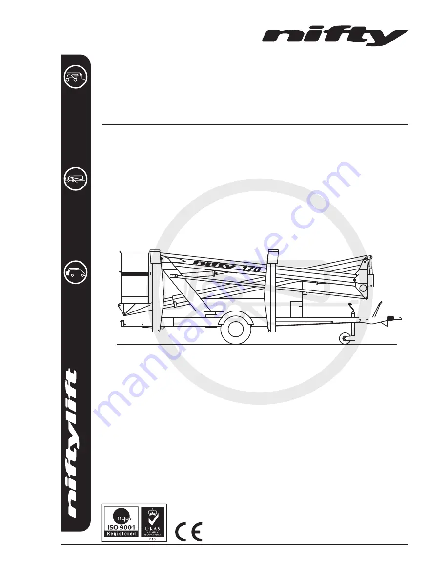
Operating and Safety Instructions

MODEL 170 (TM50) SERIES

Manufactured by:

Niftylift Limited

Fingle Drive

Stonebridge

Milton Keynes

MK13 0ER

England

www.niftylift.com

e-mail: [email protected]

Tel: +44 (0)1908 223456

Fax: +44 (0)1908 312733

M50151/08

Summary of Contents for 170H Series

Page 1: ...50 Operating and Safety Instructions MODEL 170 TM50 SERIES Manufactured by Niftylift Limited Fingle Drive Stonebridge Milton Keynes MK13 0ER England www niftylift com e mail info niftylift com Tel 44 0 1908 223456 Fax 44 0 1908 312733 M50151 08 ...

Page 2: ......

Page 3: ...l Safety Check Schedules 13 14 3 4 Placard Decals and Installation 15 20 3 5 Torque Requirements 21 4 OPERATION 4 1 Control Circuit Components 22 4 2 Setting up Procedures 23 24 4 3 Ground Control Operation 25 26 4 4 Platform Control Operation 27 28 4 5 Cage Weigh System 29 31 4 6 Batteries and Charging 32 34 4 7 Transporting Towing Craneage Storage and Setting to Work 35 38 4 8 Traction Drive 39 ...

Page 4: ...ictly forbidden One of the most important facts to remember is that any equipment is only as safe as those who operate it DANGER WARNING CAUTION IMPORTANT INSTRUCTIONS AND NOTICE Any place these topics may appear either in this manual or on the machine they are defined as follows DANGER If not correctly followed there is a high probability of serious injury or death to personnel WARNING OR CAUTION...

Page 5: ...Pty Ltd 11 Kennington Drive Tomago NSW 2322 Australia Tel 61 0 2 4964 9765 Fax 61 0 2 4964 9714 The Niftylift 170 trailer mount is an extremely versatile articulated boom platform of unique and simple design It is capable of placing two men and their tools up to a height of 17m 56ft or an outreach of 8 7m 28ft 5in The booms are mounted via a 360o powered swing mechanism on to a compact base balanc...

Page 6: ... 200kg 440lb 500lb TURRET ROTATION 360º TURRET TAILSWING Zero MAXIMUM TRAVEL SPEED 45 mph 72 kph PLATFORM SIZE LENGTH X WIDTH 0 65m x 1 1m 25in x 44in CONTROLS Full proportional hydraulic HYDRAULIC PRESSURE 200bar 2900 PSI TYRES Bi Energy Traction Drive 205 R14C 8PR 205 75 R16C8PR 4 5 bar 65 psi 4 5Bar 65 PSI GROUND CLEARANCE 26cm 10 in GROSS VEHICLE WEIGHT MAXIMUM 2200kg 4840lb MAXIMUM GROUND PRE...

Page 7: ...ATION UK PLATE 0 1 2 3 4533 3 3 63 45 1 33 45 333 1 333 78 1 0 333 5 2 0 33 9 3 333 3 333 0 00 3 2 00 33 This manufacturer s plate is attached to Boom 1 on each machine at the time of manufacture on every Niftylift Please ensure all sections have been stamped and are legible ...

Page 8: ...SA PLATE 0 1 2 3 2 1 0 4 3 4 3 2 3 5 55 2 0 0 555 1 0 555 4 0 4 3 2 4 55 2 4 5 555 5 2 555 3 33 5 4 0 33 55 4 2 This manufacturer s plate is attached to Boom 1 on each machine at the time of manufacture on every Niftylift Please ensure all sections have been stamped and are legible ...

Page 9: ...IED BODY NUMBER 0044 ADDRESS POSTFACH 10 32 61 N E S S E 1 4 1 5 4 D Y N A M R E G CERTIFICATE NUMBER APPLICABLE STANDARDS EN 280 2001 A2 2009 C E 2 4 6 0 0 2 1 4 0 2 0 6 N E N I D We hereby declare that the above mentioned machine conforms with the requirements of the Machinery Directive 2006 42 EC and EMC Directive 2004 108 EC SIGNED DATE 14th December 2009 NAME Malcolm North POSITION Engineerin...

Page 10: ...nd at the beginning of each shift the Niftylift shall be given a visual inspection and functional test including but not limited to operating and emergency controls safety devices personal protective clothing including fall protection air hydraulic and fuel system leaks cables and wiring harness loose or missing parts tyres and wheels placards warnings control markings and Operating and Safety Man...

Page 11: ...otice boards etc 2 1 15 The Niftylift shall not be operated from a position on trucks trailers railway cars floating vessels scaffolds or similar equipment unless Niftylift Ltd in Great Britain approves the application in writing 2 1 16 Always check below and around the platform before lowering or slewing to ensure that the area is clear of personnel and obstructions Care should be taken when slew...

Page 12: ...ive and protective glasses and clothing is recommended 2 1 29 When the machine is not in use always stow the booms correctly NEVER LEAVE THE KEYS IN THE MACHINE if it is to be left for any period of time Use wheel chocks if leaving on an incline 2 1 30 If the platform or elevating assembly becomes caught snagged or otherwise prevented from normal motion by adjacent structure or other obstacles suc...

Page 13: ...nge of machines does not exceed 73dB A measured at a perpendicular distance of 4m under equivalent continuous A weighted sound pressure test conditions This was based on a Diesel powered machine working under load All other models will exhibit significantly lower emissions than this figure dependant on power option In normal operation the Vibration level to which the operator is subjected will not...

Page 14: ...ial platform Carry out the Pre operational Report before placing machine in service 3 2 PREPARATION FOR USE Whilst every effort has been made at the Niftylift factory to ensure your machine arrives in a safe and operable condition it is necessary to carry out a systematic inspection prior to putting the aerial platform into service THIS IS NOT A REQUEST IT IS MANDATORY To assist the user in this t...

Page 15: ...ns and emergency stop buttons function properly 9 Check the operation of the manual hand pump 10 Visually inspect all hydraulic hoses and fittings for damage or leaks 11 Check operation of the stabiliser alarm 12 Check that outrigger footpads are secure 13 Check that the platform pivot pins and their tag bolts are secure 14 Check security and operation of the boom clamp 15 Check the operation of t...

Page 16: ...ger housings 11 Lightly oil the locating pins on outriggers 170M only 12 Oil and check the operation of manual jacks 13 Check and adjust if necessary the Nylatron studs around the telescope boom 14 Every three months check and verify the calibration of the cage weigh system See section 4 5 4 for the calibration procedure 15 Every Six months perform a thorough examination in accordance with the Lif...

Page 17: ...14864 2 14 General Warning P18672 2 15 Head Protection P14921 1 16 Serial Plate P15383 1 18 SWL 200kg P14801 1 19 Nifty 170 P26440 2 20 Niftylift com P14390 1 22 Cage levelling P10853 1 23 Hydraulic Controls 3 lever P14926 1 24 Hydraulic Controls 5 lever P14927 1 25 Base Control Cage weigh Non cage weigh P17219 P15881 1 1 26 Point Load 13 0kN P14965 4 27 Outriggers Hydraulic P14841 4 28 Outrigger ...

Page 18: ...eigh P17213 P16684 1 1 39 Operating Instructions P14892 1 41 Overload Warning P18848 2 42 Noise Warning 73dB P17123 1 43 Traction Drive Engage P18890 1 44 Hand Crush P14782 2 45 Cage Rotate P15634 1 46 Blank Axle Plate P16190 1 47 Traction Drive Release P18975 1 48 Tow hitch Australia NZ P17970 1 49 Traction Drive On slope P18976 1 ...

Page 19: ...NG TELESCOPE IN OUT 170H Series OPTIONS OPTIONS 10 26 10 4 41 23 25 2 9 28 8 8 33 37 2 41 45 14 20 11 5 19 4 7 6 27 32 30 12 27 18 27 27 19 16 48 15 29 29 29 29 29 35 38 36 39 13 42 43 44 44 24 22 13 46 4 4 4 47 49 4 11 11 11 1 6 3 14 PLATFORM CONTROLS JACK CONTROLS GROUND CONTROLS D80583 13 ALL 4 EDGES OF OUTRIGGERS 4 POSNS 4 POSNS 4 POSNS ...

Page 20: ...rols P14922 1 17 Harness Point P14883 2 18 Component Stability P19708 1 19 Manual Hand Pump P19090 1 20 Tyre Pressure 65 psi P14876 2 22 General Warning P18672 2 23 Serial Plate P15383 1 24 No Step P14785 7 25 Head Protection P14921 1 27 General Notice P18863 1 28 SWL 500lbs P17328 1 29 Daily Safety Check List P14908 1 32 Hydraulic Controls 5 lever P14927 1 33 Warning Stripes A R 34 Hydraulic Cont...

Page 21: ...01 10 19 ITEM DESCRIPTION NUMBER QTY 46 Cage Rotate P15634 1 47 Operating Instructions P14892 1 49 Noise Warning 73dB P17123 1 50 Hand Crush P14782 2 52 Traction Drive Engage P18890 1 53 Traction Drive Release P16636 1 54 Traction Drive On slope P18976 1 ...

Page 22: ...OUTRIGGERS OPTIONS OPTIONS PLATFORM CONTROLS JACK CONTROLS GROUND CONTROLS 8 17 9 47 17 10 32 2 46 1 4 12 2 1 18 22 13 11 7 39 19 28 24 24 24 4 11 11 50 12 4 4 6 4 24 20 24 24 24 33 25 4 6 24 24 24 20 24 4 6 22 43 23 4 D80162 4 24 11 8 24 15 37 24 36 33 33 33 4 46 44 34 7 50 24 27 29 45 41 54 53 52 6 3 42 TM50 Series ...

Page 23: ... QUALITY SIZE Tightening torque in ft lbs Nm GRADE 8 8 10 9 M 6 7 4 10 10 14 M 8 18 5 25 26 35 M 10 36 49 51 69 M 12 65 86 89 120 M 14 100 135 140 190 M 16 155 210 218 295 M 18 215 290 300 405 WHEEL NUTS Standard Traction Drive 110ft lbs 117ft lbs 150Nm 160Nm SLEW RING BOLTS 155ft lbs 210Nm ...

Page 24: ...ith the ground These control functions are of primary importance to safety of the machine and operator Under no circumstances should this control function be isolated or by passed 4 1 4 BATTERY ISOLATOR A grey battery isolator handle is located beneath the canopy which allows the machine control and power circuits to be isolated from the batteries themselves Under normal operation the machine Key ...

Page 25: ...ncy stops are not engaged i e fully out 8 Follow instructions below for either manual or hydraulic outrigger models MANUAL OUTRIGGER 170M MODELS 9 Leave ground control key in centre OFF position until jacks are deployed Turning this key to platform position will cause the Klaxon to sound as the outriggers will detect that the jacks are not in contact with the ground 10 All four outrigger beams mus...

Page 26: ...o minimise the risk of damaging the jockey wheel 12 Check that the base is level using the spirit level adjacent to outrigger control station 13 The booms can now be operated from the ground control station by pressing and holding the green power button Note If no power is available check that each outrigger is lowered and each footpad is taking equal weight 14 To operate the booms from the platfo...

Page 27: ...l automatically default to the primary power source usually battery PETROL GASOLINE ENGINE OR PETROL GASOLINE ELECTRIC MODELS 7 For a cold engine start go to step 8 or for a warm engine start go to step 9 8 COLD ENGINE turn the engine fuel tap ON and engage the choke lever Turn the main engine ignition through ON to ST Start and the engine will fire Return the choke lever to its normal running pos...

Page 28: ... 4 B Select lever 1 2 3 or 4 for desired boom function 1 Operates Telescope UP for out DOWN for in 2 Operates Lower Boom UP for up DOWN for down 3 Operates Upper Boom UP for up DOWN for down 4 Operates Swing UP for right DOWN for left If applicable Ground control of telescoping is optional ALWAYS ENSURE THE AERIAL PLATFORM IS ON A FIRM SURFACE AND THE AREA IS FREE OF ANY OVERHEAD OBSTRUCTIONS ENGA...

Page 29: ... manual outrigger models 170M turn the key switch at the ground control station to Platform clockwise then remove key and place in the platform control station and switch to ON clockwise 5 Battery electric models go to step 11 DIESEL ENGINE OR Bl ENERGY MODELS ONLY 6 Ensure that the main engine ignition switch is ON Turn the Engine Start switch on the platform control box clockwise and the engine ...

Page 30: ...GENCY PROCEDURES 1 Push in red emergency stop to shut down all functions 2 Use manual hand pump to provide motive power and manoeuvre the machine as normal using the hand levers Platform or Base PLATFORM CONTROL STATION BI ENERGY MODEL 4 4 2 BOOM FUNCTIONS 1 Push and hold green Power Control button 1 2 3 4 5 2 Select lever 1 2 3 4 or 5 for desired function 1 Operates Platform Lev FWD for forward B...

Page 31: ... this facility especially if the machine is significantly overloaded any motion that causes the machine outreach to increase could induce instability The machine must be manoeuvred in such a manner as to reduce outreach then height until a safe level is reached to permit the operator to dis mount or the overload to be removed 4 5 2 FUNCTION The cage overload system is powered from the machine cont...

Page 32: ...o be lost within this 5 kg limit Lock the adjustment screw securely The over travel adjusters can now be used to protect the micro switch from excess forces should a substantial overload be applied to the cage Typically if the machine is manoeuvred into contact with a fixed object snagging the cage assembly this would be detected as an overload to the system Adjust the screws forward until they co...

Page 33: ...d calibration of the weigh assembly For this reason it is not recommended to restrain the machine in transit using strap or chains passed through or over the cage itself This is particularly true of the electronic load cell system which could be permanently damaged by the application of such excessive external forces Whilst the mechanical system could be considered to be more robust in operation t...

Page 34: ...lamp batteries are fully charged DIGITAL CHARGER Pulsing Green 50 LED Batteries are charging and between 0 50 capacity Constant Green 50 LED and pulsing Green 75 LED Batteries are charging and between 50 75 capacity Constant Green 50 75 LED s plus pulsing Green 100 LED Batteries are charging and between 75 100 capacity Constant Green 50 75 100 LED s batteries are fully charged Red Gel lamp Only ap...

Page 35: ...ng an 110V supply as opposed to a 240V supply This is due to the connection of the primary coils being in parallel which in effect only allows the transformer to see 220V Similarly the capacity of the 110V supply will decide the input current available hence a small hand tool transformer will not operate the battery charger efficiently therefore charging times will increase further due to input li...

Page 36: ...eady started i e a trickle charger This can take several hours possibly days Careful monitoring of the rise of battery voltage will indicate when recovery has been achieved TOPPING UP During the course of normal operation the batteries should be inspected at least once a fortnight to check the level of electrolyte During the end of charge gassing takes place which will cause a slight reduction in ...

Page 37: ...reepage during transport does not permit the machine to come into contact with other goods being shipped or the container itself Some movement of the machine structure might occur during transit which could lead to fretting or other damage If the machine is equipped with a transit device such as a boom clamp etc this should be securely applied Strap booms carefully to constrain them from sideways ...

Page 38: ...E Coupling Instructions 1 Depress the trigger on the lever mechanism and lift the handle upwards and forward 2 Place the unlocked coupling head onto the towing ball and apply slight downward pressure The head will automatically lock onto the ball 3 Ensure that the trigger has returned to its free position before attempting to tow and that the coupling head is securely on the towing ball 4 Connect ...

Page 39: ...of charge damage dirt etc Never leave in a state of discharge for any length of time If no use of the platform is intended an occasional top up charge of the batteries will serve to equalise their charge level 3 Leave battery disconnect switch in OFF position to prevent discharge of batteries through leakage 4 If machine is to be left on an incline chock wheels to prevent creep 5 If machine is to ...

Page 40: ...anding in the cage i e with the operator standing adjacent to the cage side whilst simultaneously operating the lever and green button to move the cage Take care not to become trapped between the moving cage and a fixed object and ensure those around you are clear of the moving cage When the system has been charged in both directions the cage levelling function should be restored If the system ope...

Page 41: ...r unit to produce hydraulic flow which is directed to the drive manifold It is not necessary to operate the jack selector lever as this would deviate the hydraulic flow to the jack manifold and render the drive inoperative 4 Whilst holding the joystick button and keeping the drive lever in the upright position it is possible to use the third horizontal control lever to engage the traction drive By...

Page 42: ...ld the machine be towed with the traction drive system still engaged serious damage may result Do not use the traction drive as a brake the parking handbrake must be utilised for this purpose Never disengage the traction drive unless the handbrake is engaged OR the wheels chocked OR the machine directly and securely connected to a suitable towing vehicle Always position the machine on flat level g...

Page 43: ...to the base controls and lower platform to the ground using either platform or base controls If initial movement of the machine allows the master alarm to reset normal controls will be available This is then the fastest method of lowering the platform to the ground Note If the machine is fitted with a cage overload system and the cage comes into contact with a fixed object whilst operating at heig...

Page 44: ...ep is required so that all future Technical Bulletins are able to reach the registered owner of each machine without delay Please note warranties are not transferable 6 2 MANUAL OF RESPONSIBILITIES You are required by ANSI SIA 92 2 1990 to read and understand your responsibilities before you use or operate this aerial platform Please read the enclosed document as failure to do so could result in d...

Page 45: ...les slide freely 90 120 or are secure 170 180 Wheels are secure tyre condition acceptable Wheel bearings OK Mudguards are secure Locating pins operate freely and oiled Lock bolts are tight Wheels spin freely when handbrake is released Brakes come on equally when handbrake is applied Brake linkages and cables secure Brake shoe wear not excessive Breakaway cable fitted and operable Lighting board fi...

Page 46: ...er full range if fitted INTERNAL POWER PACK Power pack and all components secure All cables and terminals secure All hose connections secure Hoses not kinked or fouled Charger control box secure Battery secure Electrolyte level and specific gravity Charger operation Hydraulic oil level FINISH Operation of boom clamp Pivot pin tag bolts Correct decals all visible Canopy bonnets Grease nipples Feet ...

Reviews: