manualshive.com logo in svg
background image


Quick Start Guide:  LPC1768-Xplorer                                                        


1


www.ngxtechnologies.com
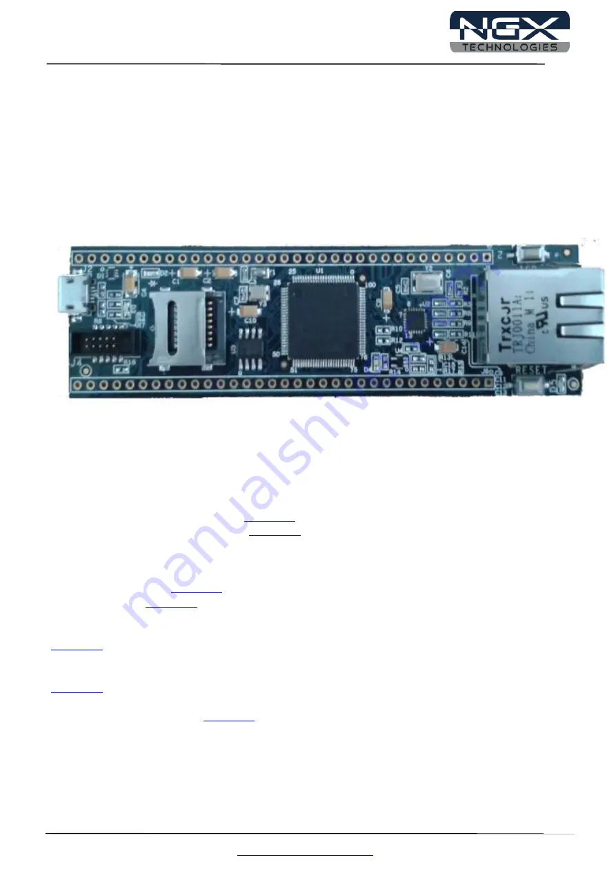


LPC1768-Xplorer 


Fig. 1 


User Manuals for Xplorer: 


For KEIL MDK-ARM with ULINK2

Click here


For LPC-Xpresso with NXP-LPCLink: 

Click here


Sample projects for Xplorer: 

 
For KEIL MDK-ARM: 

Click here


For LPC-Xpresso: 

Click here


Schematic for Xplorer Board:


Click here

 to download Schematic. 


USB Virtual Com INF file:


Click here

 to download USB Virtual Com INF file. 


Secondary USB Bootloader: 

Click here


Содержание LPC1768-Xplorer

Страница 1: ...RM with ULINK2 Click here For LPC Xpresso with NXP LPCLink Click here Sample projects for Xplorer For KEIL MDK ARM Click here For LPC Xpresso Click here Schematic for Xplorer Board Click here to download Schematic USB Virtual Com INF file Click here to download USB Virtual Com INF file Secondary USB Bootloader Click here ...

Страница 2: ...M0 M3 M4 microcontrollers Our experience with developing evaluation platforms for NXP controller enables us to provide solutions with shortened development time thereby ensuring reduced time to market and lower development costs for our customers Our cost effective and feature rich development tool offering serves as a testimony for our expertise cost effectiveness and quality Contact Information ...

Страница 3: ...8 Xplorer Overview 6 2 1 Introduction 6 2 2 Board Features 6 2 3 BLOCK DIAGRAM 7 2 4 LPC1768 description 7 3 0 LPC1768 Xplorer verification 9 3 1 Board Image with pointers to the peripherals 9 3 2 Powering the Board 10 3 3 Verifying all the peripherals on LPC1768 Xplorer 10 3 3 1 LED 16 3 3 2 USB Virtual COM port 16 3 3 3 User Input Switch 19 3 3 4 Micro SD connector 19 3 3 5 I2C EEPROM 20 3 3 6 E...

Страница 4: ...Link with IAR Embedded Workbench or KEIL uVision 1 2 ARM JTAG 20 pin to Cortex JTAG 10 pin Adaptor Please note that your existing debugger might be supporting only the 20 pin ARM JTAG connector In such scenarios one would require a 20 pin to 10 pin adaptor and the necessary cables The Xplorer has on board Cortex SWD JTAG 10 pin male connector the 20 pin to 10 pin adaptor is not a part of the Xplor...

Страница 5: ...ard with ULINK2 and KEIL IDE Fig 3 1 4 NXP LPCLink and LPCXpresso Separate the LPCXpresso controller part and use only the NXP LPCLink as shown in the below image Fig 4 The Xplorer board has on board Cortex SWD JTAG 10 pin box the one end of the 10 pin cable is connected to LPCLink and the other end is connected to Xplorer Make sure the 10 pin cable notch on the connector is facing towards the arr...

Страница 6: ...aces like the SWD JTAG you can use this platform with any tool For our development we use ULINK and KEIL as the debugger and compiler IDE respectively The board is supported by extensive sample examples allowing you to focus on the application development 2 2 Board Features Following are the salient features of the board Dimensions 101mm X 27mm Controller LPC1768 100 pin LQFP PCB 2 layer RoHS comp...

Страница 7: ... prefetch unit that supports speculative branches The peripheral complement of the LPC1768 includes up to 512 kB of flash memory up to 64 kB of data memory Ethernet MAC a USB interface that can be configured as either Host Device or OTG 8 channel general purpose DMA controller 4 UARTs 2 CAN channels 2 SSP controllers SPI interface 3 I2C interfaces 2 input plus 2 output IS interface 8 channel 12 bi...

Страница 8: ...200 kHz and multiple result registers 10 bit Digital to Analog Converter DAC with dedicated conversion timer and DMA support 70 100 pin package General Purpose I O GPIO pins with configurable pull up down resistors open drain mode and repeater mode Real Time Clock RTC with a separate power domain Watchdog Timer WDT The WDT can be clocked from the internal RC oscillator the RTC oscillator or the AP...

Страница 9: ...gramming Also this exercise helps you get acclimatized with the board quickly To run the tests you will need the following LPC1768 Xplorer Power USB cable you can power it through USB port or external power supply Alternatively the Xplorer has a 5V in pin available for powering through external power source PC With Windows7 or XP 32 bit One USB ARM to Micro B cable in addition to the one provided ...

Страница 10: ...The test firmware is designed in a manner that the user needs to spend as minimum time as possible to verify all the on board peripherals The test firmware executable resides on the Flash Note The test firmware Debug Messages or flow might be changed in due course Generally these are only cosmetic changes so that the usage is easier If you observe a different message than the one mentioned in the ...

Страница 11: ...nstall the VCOM drivers on Windows 7 machine Step 1 Connect USB to the computer Open Device Manager You can find NXP LPC17xx VCOM new device listed under Other devices Fig 7 Step 2 Next Right click on the NXP LPC17xx VCOM and then left click on Update Driver Software Fig 8 ...

Страница 12: ...tart Guide LPC1768 Xplorer 12 www ngxtechnologies com Step 3 Click on Browse my computer for driver software Fig 9 Step 4 Left click on Browse Select lpc17xx vcom inf driver folder and then click on OK Fig 10 ...

Страница 13: ...Quick Start Guide LPC1768 Xplorer 13 www ngxtechnologies com Step 5 Click on Next to continue driver installation Fig 11 Step 6 Click on Install this driver software anyway Fig 12 ...

Страница 14: ...vice manager Please note that the COM port list under the Device Manager is automatically updated with the COM port number for the Virtual COM On our test machine we see two COM ports listed COM1 and COM12 COM1 is the actual COM port and COM12 is the virtual COM port The COM12 will appear only if the Xplorer board is connected USB to the PC Every time the Xplorer is reset the user needs to close t...

Страница 15: ...ripherals are verified by the firmware are as follows Test Firmware Flowchart NO YES NO YES START Is VCOM Enumeration Completed A RTC Verification Xplorer peripheral initialization Wait for user input Flag 1 SD card Verification I2C EEPROM Verification LED Blink D4 A B B Ethernet PHY Verification ...

Страница 16: ...he Xplorer has one Green LED This LED connected to the one of the GPIO line Please refer to the schematics for more details 3 3 2 USB Virtual COM port Test setup and verification For the very first time the Windows machine will ask for the appropriate Virtual COM drivers to be installed Steps to select USB VCOM port on HyperTerminal in Windows 7 machine Step 1 Open a HyperTerminal Enter the name a...

Страница 17: ...Quick Start Guide LPC1768 Xplorer 17 www ngxtechnologies com Step 2 Select USB Vcom Port COM12 and then click on OK Fig 16 Step 3 Click on Restore Defaults and then click on OK Fig 17 ...

Страница 18: ...18 www ngxtechnologies com Step 4 Now the USB VCom is ready to use Fig 18 Note You would not be able to proceed with the verification unless the Virtual COM drivers are installed The firmware waits for the USB to enumerate as VCOM port ...

Страница 19: ...t the debug messages on the VCOM port can be viewed from the start of the test Without this synchronization the test firmware would proceed with the debug messages being displayed while the user is still configuring the Hyper Terminal or other serial emulation tool Fig 19 3 3 4 Micro SD connector Test setup and verification The firmware validates the micro SD card interface by writing and reading ...

Страница 20: ...Start Guide LPC1768 Xplorer 20 www ngxtechnologies com Fig 20 3 3 5 I2C EEPROM Test setup and verification The firmware validates the I2C EEPROM the result of this test is displayed over the VCOM port Fig 21 ...

Страница 21: ...w ngxtechnologies com 3 3 6 Ethernet Test setup and verification The test firmware configures the Xplorer board as a Webserver Fig 22 The Ethernet interface can be verified by either using a PING command in the windows command prompt Fig 23 ...

Страница 22: ...s configured as 192 168 1 123 Type the same IP address in the browser Clicking the ON button will TURN ON LED D4 and clicking OFF button will TURN OFF LED D4 Fig 24 3 3 7 RTC Test setup and verification The firmware validates the internal RTC The time and date are displayed over the VCOM port Fig 25 ...

Страница 23: ...Quick Start Guide LPC1768 Xplorer 23 www ngxtechnologies com 4 0 CHANGE HISTORY 4 1 Change History Rev Changes Date dd mm yy By 1 0 Initial release of the Quick Start Guide 25 06 2012 Veeresh Tumbaragi ...

Страница 24: ...ical requirements of these directives or other related directives The user assumes all responsibility and liability for proper and safe handling of the goods Further the user indemnifies NGX Technologies from all claims arising from the handling or use of the goods Due to the open construction of the product it is the user s responsibility to take any and all appropriate precautions with regard to...

Страница 25: ...ion and shall have no liability for the consequences of use of such information NGX Technologies reserves the right to make changes to information published in this document at any time and without notice including without limitation specifications and product descriptions This document replaces and supersedes all information supplied prior to the publication hereof Trademarks All referenced trade...

Отзывы: