Nexo RS18, User Manual
The Curtis RS18 is a high-quality audio receiver designed to enhance your home entertainment experience. With a sleek design and powerful functionality, it delivers exceptional sound quality and versatile connectivity options. Find the detailed specification sheet and free downloadable manual on our website, ensuring you get the most out of your Curtis RS18.
Share
Download


Reviews:
No comments
Related manuals for RS18

SB26 soundbar
Brand: Harman Kardon Pages: 15

CITATION SUB
Brand: Harman Kardon Pages: 2

SW-400 Mark II
Brand: Aaron Pages: 3

PASSIO SUB 15
Brand: K&F Pages: 18

SWE-1241
Brand: Alpine Pages: 4

TNT-15 Sub
Brand: FAME Pages: 57

AWIS-12
Brand: AudioBahn Pages: 19

Grand Touring GTO1204BP
Brand: JBL Pages: 2

arco 12 sub
Brand: DAS Pages: 2

GTr 8120 A
Brand: Blaupunkt Pages: 8

Overdrive ODw1000
Brand: Blaupunkt Pages: 19

CXB10A
Brand: Citronic Pages: 4

RBS 1
Brand: Peavey Pages: 2

PV 118 Sub
Brand: Peavey Pages: 2

QW-118
Brand: Peavey Pages: 4

OM-605
Brand: Paradigm Reference Pages: 28
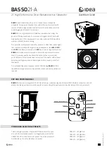
BASSO21-A
Brand: Idea Pages: 4

HRS150
Brand: Mackie Pages: 20


