

175-100290-01 REV C | September 2012
Page 1 of 2
6.3
NEXIO Farad 2300 Quick Start Guide
4. Rack Installation
NOTE: The front Bezel MUST be installed to maintain compliance
with worldwide EMI standards.
NEXIO Farad documentation can be downloaded from the Harris
Website at http://ecustomer.broadcast.harris.com. After logging in,
go to Self Service > Review Documentation > Servers > Storage
Systems > NEXIO Farad. The following documents are relevant to
Farad installation.
• Farad Infrastructure Commissioning Checklist.XLS: Instructions on
setting up Farad systems.
• DH_RBKI_83-00004524-13-01-B.PDF: Rackmount Kit Instructions.
• Assured SAN_PRCS_83----5172-11-01-A.PDF: Product
Regulatory Compliance and Safety Information.
1. Farad Documentation
2. Electrical Requirements
Supply rails must be sized to withstand a maximum load of 500W per
Core or Store during the
fi
rst 10 seconds after power applied. Steady
state load is 314W per Core or 150W per Store after the time elapses.
If both power rails are active, the load will split across the rails.
3. Unpacking the Storage System
Before unpacking, inspect all packages for evidence of damage during
transit. If there is evidence of damage, contact Customer Support.
3.1 Unpacking the Storage System:
1
. Position packaging close to the place where the equipment is to be
installed.
2
. Open the box and remove all accessory bags and set them aside.
3
. Remove the foam components from the top of the container.
4
. Open the protective plastic wrapping.
5
. Lift the enclosure from the box and place it on a stable work surface.
You should reduce the overall weight of the enclosure by removing
the Power Supply Unit (PSU) and top row of drives before lifting the
enclosure from the box.
3.2 Removing PSUs:
You can reduce the weight of the enclosure by removing the PSUs and
some of the drives before taking the enclosure out of the box.
1.
Remove foam components and open the plastic wrapping so you
can access the rear of the chassis.
2.
Lift the rear side of the chassis up so the PSUs are accessible.
3.
Turn the thumbscrew at the top of the latch counterclockwise to
loosen and disengage it from the module.
DO NOT
remove the
thumbscrew from the latch. (
Figure 1
)
4
. Rotate the latch downward about 45 degrees while supplying
leverage to disconnect the module from the internal connector.
(Figure 1)
Figure 1 - Removing PSU
Once the enclosure has been installed into the rack, insert the PSU back
into the chassis using the reverse process.
1
. Orient the PSU with the AC connector toward the right.
2
. With the latch in the open position, slide the module into the
appropriate power supply slot as far as it will go.
3
. Rotate the PSU latch upward until it is
fl
ush against the PSU face,
ensuring that the connector on the PSU engages the controller inside
the chassis.
4
. Tighten the thumbscrew at the top of the power supply latch clockwise
to secure the latch to the PSU within the enclosure.
5
. Repeat for the second PSU. Both PSUs must be installed before you
power up the chassis.
5.
Use the latch to pull the module straight out of the chassis.
6
. Repeat steps 3, 4, and 5 for the second PSU.
7
. Lower the rear side of the chassis back down into the shipping box
so you can lift the front side up to remove drives as described in the
Removing Disk Drives
section.
3.3 Removing Disk Drives
Removing disk drives will reduce the weight of the enclosure and make it
easier to lift out of the box and install into its rack.
1
. Remove foam components and open the plastic wrapping.
2
. Lift the front side of the chassis to access the top row of drives.
3
. Release the latch to disengage the module. Move the latch to the left
to eject the disk from its position within the drive slot. (
Figure 2
)
Figure 2 - Slide Latch to the Left
Figure 3 - Remove Drive
Figure 4 - Insert Drive
4.
Grab the module
fi
rmly and pull it straight out of the chassis slot.
(
Figure 3
) Repeat for all drives to be removed.
Once the enclosure is installed in the rack,
insert the drives back into the chassis.
1
. With the LEDs on the left side, slide the
disk drive into the slot until it clicks into
place. (
Figure 4
)
2
. Repeat for all drives. The chassis must
be fully populated with drives before you
power up.
4.1 Rack Installation Pre-Requisites
• The NXS2312 enclosures are designed to be installed in an industry
standard 19-inch cabinet. See the
Farad Infrastructure Commissioning
Checklist
for detailed information about rack compatibility and how to get
rack kits for non-standard cabinets.
• The fully populated enclosure can weight up to 27 kg (60 lb). You
should not lift a fully populated enclosure by yourself. (See sections
3.2
and
3.3
of this document for instructions on how to reduce the weight
by removing PSUs and disk drives.)
4.2 Rack Installation Procedures
• See the printed material included in the rackmount bracket kit for
installation details.
• After the enclosure is installed, insert the PSU and drives that were
removed.
• The front bezel
MUST
be installed to maintain compliance with
worldwide EMI standards. (See
Section 5
for bezel installation details.)
5. Front Bezel Installation
5.1 EMI Warning
• The front bezel
MUST
be installed to maintain compliance
with worldwide EMI standards.
5.2 Bezel Installation
No screws are needed. The bezel is kept in place by its
fi
t
and by magnets on each side of the unit.
• Orient the bezel so the smoked plastic window is on the
left and the light pipes are on the right. (
Figure 5
)
• Fit the bezel onto the front of the chassis. Be sure that the
bended edges across the top and bottom of the bezel fully
insert into the chassis.
6. Setup and Cabling
Figure 5 - Bezel Orientation
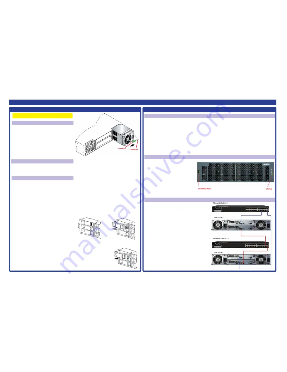
Figure 6 - Attaching Ethernet Switches to Cores
6.1 SFPs
• The NXS2312 Core units come with SFPs already installed in the
controller modules. Each controller comes with four 8Gps SFPs. All
SFPs must be installed - 8 per core - for proper functionality even if
not all SFPs have
fi
ber channel cables attached.
6.2 Cables
• Cables included with Cores and Stores: power cables.
• Cables included with Cores only: 1.5m USB to MiniUSB cable,
1.0m MiniSAS cable, 20’ Ethernet cable, RS232 to RCA cable
4-5m FC cables.
• Cables included with Stores only: two 0.6m SAS cables.
6.3 Cabling the Enclosures
•
See
Figures 6, 7, 8 and 9
for information on cabling enclosures.
For more details, refer to the
Farad Infrastructure Commissioning
Checklist
, the
NEXIO Farad (Gen 2) Setup Guide
and the
NEXIO
Farad (Gen 2) Service Guide
.
• Rack post to post depth min. 635mm (25”) to max. 915mm (36”).
• Leave a minimum of 153mm (6”) at the front and back of each enclosure
to ensure adequate air
fl
ow for cooling. No clearance is required on the
sides, top, or bottom of the enclosures.


