Nexcom NDiS 541, User Manual
The Nexcom NDiS 541 User Manual is a comprehensive guide to help you effortlessly navigate and optimize your experience with this cutting-edge product. With easy-to-follow instructions and detailed illustrations, this manual can be downloaded for free from our website, ensuring you have all the information you need at your fingertips.
Share
Download


Reviews:
No comments
Related manuals for NDiS 541

DVD-C631P
Brand: Samsung Pages: 24

Qplay QPD555B
Brand: SONIQ Pages: 12

VBR333
Brand: Vizio Pages: 16

MPK1041
Brand: Curtis Pages: 35

PV-500EVO2
Brand: Lawmate Pages: 34

NMP-600 - Network Media Player Connects
Brand: ViewSonic Pages: 2

TOUCH SCREEN EMP588-4
Brand: Emerson Pages: 31

Research MP530
Brand: Emerson Pages: 36

Research MP250
Brand: Emerson Pages: 44

DMB Plus
Brand: Mpio Pages: 45

MyChannel DSM-350
Brand: D-Link Pages: 58

A505
Brand: Hott Pages: 16

PC14DAB
Brand: LG Pages: 16

MF-PD330
Brand: LG Pages: 20
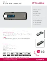
UP-SAL2GSSI
Brand: LG Pages: 1

UP3 FLAT
Brand: LG Pages: 9

UP-SAL1GSSI
Brand: LG Pages: 1

Touch Slim V25
Brand: LG Pages: 29


