55
O
Rotate
360
O
Rotate
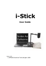
SB Module
MB Module
8 PCS LED IR
Illuminator
Board Plate
Dehumidifier
Packet
Bracket
Latch
Line out Line in
Etherent / PoE
Micro SD
DI/O
Reset
Default
DC12V/
AC24V
Heater module
Quick Installation Guide
Ver.A (P/N: 60177A0389X00
Accessories
DI/O Pin Definition & Waterproof Connector Description
DI/DO & Function Description
Placement sticker
Dehumidifier packet
Quick guide
2-axis cable concealed
wall mount bracket
Sunshield
Waterproof
connector
Wall mount
base
CD (User
Manual)
Mounting accessory
kit
DI/O
POWER
5 4 3 2 1
2 1
Gasket
Tightening
collar
Waterproof
connector
Seal nut
Strain relief
Main body
RJ45
PHONE
JACK
Push Lock
q
w
e
r
t
MB Module
DI/O
1
ALM_IN (+)
2
ALM_IN (-)
3
ALM_out_NC
4
ALM_out_COM
5
ALM_out_NO
POWER
1
AV24V/DC12V (+)
2
AV24V/DC12V (-)
Cable Wiring Description
Cable Installation Steps:
1. Run the cable inside the wall mount bracket and out through
the cable opening at the front.
2. Press down the push-lock mechanism and secure the
camera onto the push-lock. Wire the network cables to
the waterproof connector on the right, and wire the line-
in, line-out, DC 12V/AV 24V, DI/O and other cables to the
waterproof connector on the left. Tighten the waterproof
connector after all the cables are secured in place.
3. Secure the camera onto the wall mount bracket using the
two screws provided.
4. Open the camera's top cover to access the wired cables.
Install the RJ45 connector to the Ethernet cable and plug it
into the corresponding port on the MB module.
5. Close the camera's top cover and secure it with the supplied
hardware tool to complete.