New Holland T8.295, Service Manual
The New Holland T8.295 Service Manual is a comprehensive guide for owners and technicians, providing detailed instructions and maintenance procedures. Easily downloadable for free at manualshive.com, this manual ensures optimal performance and longevity for your New Holland T8.295, making it an indispensable resource for all users.
Share
Download


Reviews:
No comments
Related manuals for T8.295
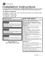
Universal II
Brand: GEAppliances Pages: 16

TRANSCAR Series
Brand: GOLDONI Pages: 154

3208
Brand: Cub Cadet Pages: 48

DSP10
Brand: Bush Hog Pages: 54

266H Wheel Horse 72052
Brand: Toro Pages: 40

72110
Brand: Toro Pages: 40

265H Wheel Horse
Brand: Toro Pages: 40

T264
Brand: TYM Pages: 215

S-V2
Brand: Summit Pages: 35

LL4100
Brand: LS tractor Pages: 46

LL2100
Brand: LS tractor Pages: 46

LB3100
Brand: LS tractor Pages: 61

LB1100 Series
Brand: LS tractor Pages: 64

J2020H
Brand: LS tractor Pages: 101

R4041
Brand: LS tractor Pages: 125

J2023H
Brand: LS tractor Pages: 113

G3033
Brand: LS tractor Pages: 112

MT122
Brand: LS tractor Pages: 132


