background image


MAN085 Rev Date 8/30/2007
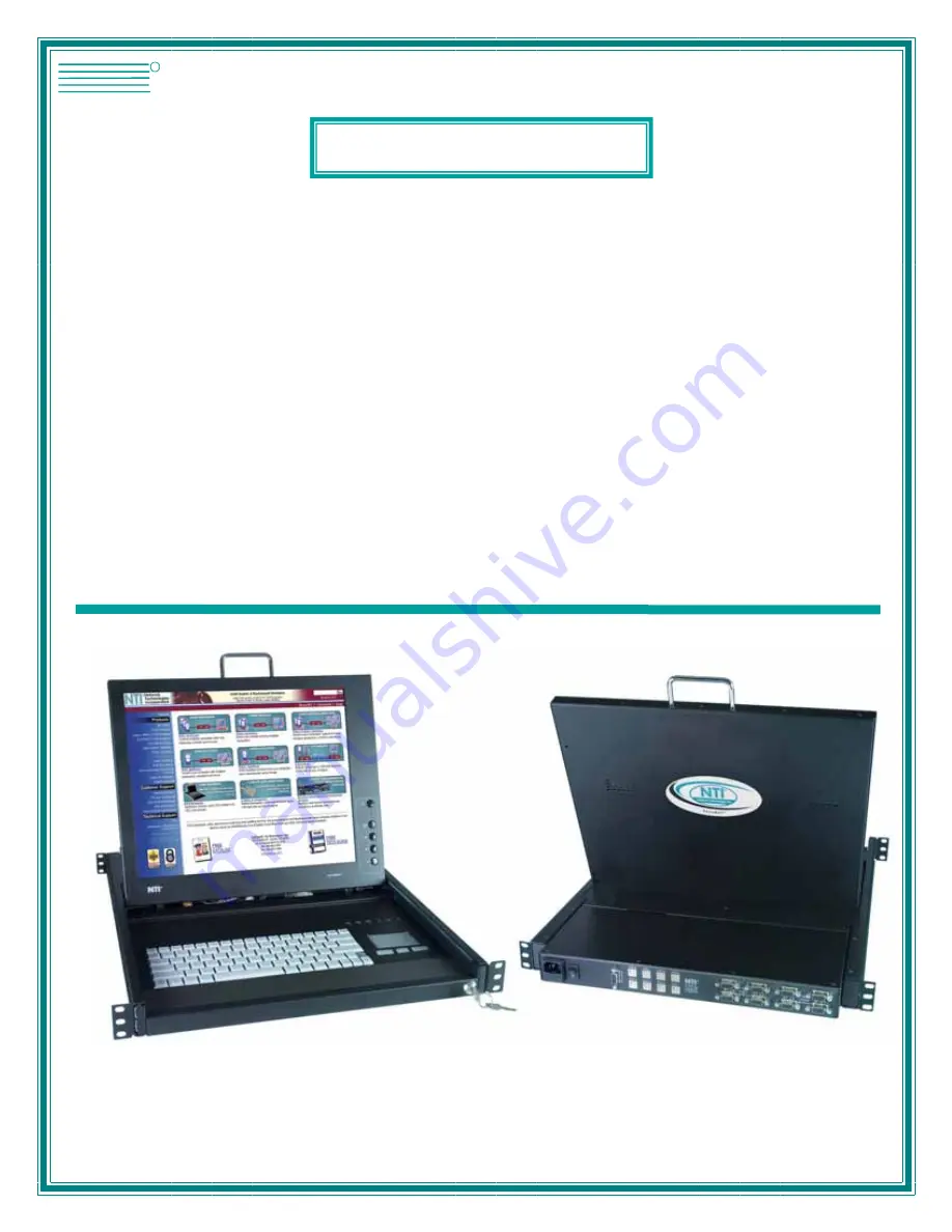


RACKMUX-V15-4USB 
RACKMUX-V15-8USB 
RACKMUX-V17-4USB 
RACKMUX-V17-8USB 


KVM Drawer with USB KVM Switch 

Installation and Operation Manual 


RACKMUX


®

Series


NETWORK
TECHNOLOGIES
INCORPORATED

Tel:330-562-7070
Fax:330-562-1999

1275 Danner Dr
Aurora, OH 44202

  www.networktechinc.com

NTI

R

Summary of Contents for RACKMUX-V15-4USB

Page 1: ... V15 8USB RACKMUX V17 4USB RACKMUX V17 8USB KVM Drawer with USB KVM Switch Installation and Operation Manual RACKMUX Series NETWORK TECHNOLOGIES INCORPORATED Tel 330 562 7070 Fax 330 562 1999 1275 Danner Dr Aurora OH 44202 www networktechinc com NTI R ...

Page 2: ...s Inc All rights reserved No part of this publication may be reproduced stored in a retrieval system or transmitted in any form or by any means electronic mechanical photocopying recording or otherwise without the prior written consent of Network Technologies Inc 1275 Danner Drive Aurora Ohio 44202 CHANGES The material in this guide is for information only and is subject to change without notice N...

Page 3: ...1 USER ACCESS FUNCTIONS 11 Introduction 11 Command Mode 11 Broadcast Mode 13 Scan Mode 13 Normal Mode 13 Edit Mode 13 Change Settings 14 Select Ports For Broadcast 15 Select Ports For Scan 15 Language Selection 16 MAC Ports Configuration 16 Search Mode 17 Maintenance Mode 17 Help Mode 18 F3 Display Information 19 No Sun Sleep Mode 19 CASCADING 20 Cascaded Installation 20 Limitations 22 Display Fun...

Page 4: ... 12 Edit Mode screen 13 Figure 13 Change Settings menu 14 Figure 14 Select ports for broadcasting 15 Figure 15 Select ports for scanning 15 Figure 16 Select the keyboard language 16 Figure 17 Configure Ports for MAC screen 16 Figure 18 Search Mode screen 17 Figure 19 Maintenance Mode screen 17 Figure 20 Information provided by the F3 command 19 Figure 21 Connections for Cascading 20 Figure 22 Casc...

Page 5: ... switch control and security administration Models Available RACKMUX V15 4USB KVM Drawer with 15 TFT LCD monitor and 4 port UNIMUX RACKMUX V17 4USB KVM Drawer with 17 TFT LCD monitor and 4 port UNIMUX RACKMUX V15 8USB KVM Drawer with 15 TFT LCD monitor and 8 port UNIMUX RACKMUX V17 8USB KVM Drawer with 17 TFT LCD monitor and 8 port UNIMUX Types of CPUs Supported Any USB CPU supporting USB version ...

Page 6: ...s and cage nuts for mounting to a rack CD with pdf of this manual Materials Not supplied but REQUIRED A USBVEXT xx MM cable for each USB CPU being connected to the switch must be used for monitor keyboard and mouse interface where xx is the length of the cable in feet MM indicates male to male connector Cables can be purchased from Network Technologies Inc by calling 800 742 8324 800 RGB TECH in t...

Page 7: ... is ON 10 Fn LED illuminates when Function Features page 26 are enabled 11 LCD Display for viewing the video signal from the connected CPU 12 Auto Shut OFF switch automatically shuts OFF the LCD display when the monitor is folded down 13 3 button touch pad for controlling mouse movements on the monitor and controlling the computer 14 Keylock to prevent unauthorized use of the RACKMUX 15 keyboard f...

Page 8: ... on each side 4 Slide the drawer in until the top holes in the front bracket flanges line up with the holes marked in step 1 Secure the front brackets on the drawer to the front cabinet rails with two screws per bracket Be sure to tighten the screws securely Then tighten the nuts applied in step 3 5 Apply one more screw to each of the rear brackets to finish Figure 1 Mount RACKMUX to rack Connect ...

Page 9: ...r ON it should be powered after connecting to and powering ON the UNIMUX switch IEC Power Cord CPU 4 CPU 3 CPU 2 CPU 1 CPU 8 CPU 7 CPU 6 CPU 5 8 4 7 3 6 2 5 1 VIDEO VIDEO NETWORK TECHNOLOGIES INC Tel 330 562 7070 1275 Danner Dr Aurora OH 44202 www nti1 com Rear View of UNIMUX in RACKMUX V15 8USB NTI Tel 330 562 7070 Fax 330 562 1999 1275 Danner Dr Aurora OH 44202 www nti1 com R CPU 4 CPU 3 CPU 2 C...

Page 10: ...rol access to CPU ports for each user Up to 63 users can be created These users have controlled access to any CPU Only the administrator can activate or deactivate the security features Security can be activated from the Maintenance Mode menu page 17 with a successful administrator login for verification purposes Furthermore the administrator can set a maximum idle time value after which the curre...

Page 11: ...r this information Once logged in a user can follow the Command Mode functions described on page 10 to control the switch within the limitations as determined by the administrator User Login Mode User login mode requires a user to login with a user name and password from the list created by the administrator This mode will also disable use of the front panel until the user logs in Function Keystro...

Page 12: ...Hot Key Figure 6 Administration Mode menu Selects the idle time in minutes Exit Administration Mode and return to previous mode Administrator Password To change the administrator password press C from the Administration Mode menu The administrator is able to change the administrator password as needed see Fig 7 Two edit fields are available one for password the other for verify password The passwo...

Page 13: ...y be up to 12 characters long may not contain spaces and are not case sensitive Passwords may be up to 15 characters long may not contain spaces and are case sensitive Function Keystroke Select previous user in the list Select next user in the list Scroll the list with one page up Scroll the list with one page down Edit selected user settings Enter Edit User Mode Exit the USER NAME LIST and return...

Page 14: ...cribes the functions available in the Edit User mode Function Keystroke Add a character to user name string password string or verify password string whichever is selected Switch sequentially between the User Name edit box Password edit box Verify Password edit box and User Access List Navigate through User Access List when it is active Toggle access rights check uncheck of the highlighted port in...

Page 15: ...e After setting it the user can enter into Command Mode either with Ctrl or with Ctrl Alternative Command Hot Key combination To disable it the administrator should set as the Alternate Command Hot Key USER ACCESS FUNCTIONS Introduction The OSD menu enables a user to name the CPUs connected to the UNIMUX switch and connect to them using that name The OSD is positioned on the monitor displaying 8 C...

Page 16: ... and clicking Clicking twice on a selected port will switch to that port and exit Command Mode To change the displayed ports on the screen simply click on the up and down arrows located to the right of the port names displayed F1 End Enter Home Esc A Z 0 9 Type any alphabetical or numeric character F3 Display information about the selected port When pressed a window displays the port name and its ...

Page 17: ...oard and mouse must remain idle for the full scan dwell time before the switch selects the next active port Note The scan dwell time set by the user only effects that user and has no effect on other switch users Normal Mode When the UNIMUX switch is not in Command or Scan mode the user is in Normal Mode controlling the CPU to which the user is connected through the UNIMUX switch Edit Mode NOTE Edi...

Page 18: ...Change Settings menu functions available from the keyboard Function Keystroke Go to Broadcast Mode Configuration Go to Scan Mode Configuration Go to Language Selection Menu Option only available if the administrator is logged in Change the scan dwell time period Configure ports for MAC or non MAC CPUs Administrator only Enable Disable right mouse button click emulation Exit from Change Settings Re...

Page 19: ... display will return to the Change Settings menu The broadcast selection list is automatically saved Figure 14 Select ports for broadcasting Select Ports For Scan To Select Ports For Scanning press S from the Change Settings menu described on page 14 The Select Ports For Scan menu enables the user to select specific ports to be active in Scan Mode Only the selected ports will be scanned in Scan Mo...

Page 20: ...lation time or whenever necessary After setting the configuration is stored in non volatile memory and will be retrieved whenever the switch is power ON When the port is connected to a Windows or SUN CPU this configuration SHOULD BE DISABLED By default all ports are configured as non MAC CPUs Windows and SUN NOTE If a port is configured as connected to a non MAC CPU but is in fact connected to a M...

Page 21: ...nd select the best matching CPU name Exit Search Mode return to Command Mode Switch to selected port Figure 18 Search Mode screen Maintenance Mode To enter Maintenance Mode press Ctrl M from the Command Mode menu Maintenance Mode enables a user to customize the On Screen Display to their requirements Function Keystroke Reset all of the port names Toggle between numeric and alphabetic listing of po...

Page 22: ...ress the F1 key from the Command Mode menu see page 11 Help Mode displays a list of commands with a short explanation of their function These lists are organized in pages for each mode i e COMMAND EDIT and SEARCH The following options enable the user to quickly obtain information on any command Function Keystroke View the previous page of help if available View the next page of help if available E...

Page 23: ...Level 1 and through port 3 of the slave connected to port 4 Level 2 See Fig 20 below Figure 20 Information provided by the F3 command No Sun Sleep Mode PLEASE NOTE It is necessary to configure a Sun CPU most versions such that the Sleep Mode is not enabled If the Sun CPU goes into Sleep Mode either automatically or manually the user must reboot the Sun CPU in order to resume use of the Sun CPU To ...

Page 24: ...or all multi user switches but not a combination of both Cascaded Installation a Using the 15HD video cable ends of a USBVEXT xx MM cable connect the USB KVM slave s MONITOR port to the master s VIDEO 1 port b Using the USB ends of the same USBVEXT xx MM cable connect one of the USB slave s USB DEVICES ports to the master s CPU 1 port Note Only one of the two ports labeled DEVICES on a slave needs...

Page 25: ... 8 CABLES UNIMUX 4X8 SLAVE CPU PORTS USER PORTS CPU17 CPU 24 USBVEXT xx MM 8 CABLES TO USER PORT 3 ON SLAVES 1 4 TO USER PORT 4 ON SLAVES 1 4 TO USER PORT 2 ON SLAVES 1 4 USBVEXT xx MM USBVEXT xx MM USBVEXT xx MM USBVEXT xx MM USER PORT 1 USER PORT 1 USER PORT 1 USER PORT 1 CPU 8 DEVICES CPU 7 CPU 6 CPU 5 CPU 4 CPU 3 CPU 2 CPU 1 5VDC 2A V I D E O 8 NETWORK TECHNOLOGIES INCORPORATED 1275 Danner Dri...

Page 26: ...he front panel buttons found on most UNIMUX switches are only used to operate standalone switches To control a cascaded network of switches only the OSD commands within Command Mode will be recognized MONITOR 1 MONITOR 2 MONITOR 3 MONITOR 4 USER 1 USER 2 USER 3 USER 4 R S 2 3 2 NTI R CPU 16 MONITOR 1 MONITOR 2 MONITOR 3 MONITOR 4 USER 1 USER 2 USER 3 USER 4 R S 2 3 2 NTI R CPU 16 SLAVE 2 UNIMUX 4X...

Page 27: ... The Up and Down Arrow buttons are used to navigate through the menus Move the cursor up or down as desired to highlight an item for selection Once an item is highlighted pressing the Menu button will select it Figure 25 OSD Controls The Select button is used to make selections within the OSD menus when the OSD menu is ON When the OSD menu is OFF the Select button will act as an Auto Adjust button...

Page 28: ...h the RED GREEN or BLUE sections highlighted use the Up or Down arrow to move between them press the Select button to choose the option to adjust Then use the Up or Down Arrow to adjust the setting Select EXIT when finished to return to the Main Menu Position Menu Selecting the Position menu will bring up a screen in which the user can select AUTO ADJUST to automatically adjust the horizontal and ...

Page 29: ... idle before the OSD menu automatically exits adjustable from 10 to 60 seconds LANGUAGE the language that the OSD menus will be presented in With the item highlighted use the Up or Down arrow to move between them press the Select button to choose the option to adjust Then use the Up or Down Arrow to adjust the setting as needed Select EXIT when finished to return to the Main Menu OSD Image can be ...

Page 30: ...hem Use the LEDs to know what special features are enabled Figure 26 US English Keyboard Layout Figure 27 Keyboard LED Indications ESC F1 F2 F3 F4 F5 F6 F7 F8 F9 F10 F11 F12 NUMLCK PRT SC INSERT DELETE SYS RQ PAUSE BREAK SCR LCK ENTER BACKSPACE 0 9 8 7 6 5 4 3 2 1 TAB CAPS LOCK SHIFT CTRL ALT Fn ALT CTRL END PG DN HOME PG UP SHIFT Z X C V B N M A S D F G H J K L Q W E R T Y U I O P 1 2 3 6 5 4 7 8...

Page 31: ...illuminate With the Fn and NumLock LEDs illuminated pressing some standard keys will result in displaying characters as indicated in the chart below Standard Key Displayed when NumLock is ON Function when NumLock is OFF j 1 End k 2 Down Arrow l 3 Page Down u 4 Left Arrow j 5 o 6 Right Arrow 7 7 Home 8 8 Up Arrow 9 9 Page Up m 0 Insert period period Delete forward slash forward slash semicolon plus...

Page 32: ...ete Sys Rq System Requirements Pause Break Up Arrow Page Up Down Arrow Page Down Left Arrow Home Right Arrow End Figure 29 Additional multi function keys SUN Keyboard Keys Use the chart below to type SUN s additional keys when the Fn key is locked RACKMUX Keyboard Sun Extra Keys RACKMUX Keyboard Sun Extra Keys F1 Stop F9 Find F2 Again F10 Cut F3 Props F11 Help F4 Undo F12 Compose F5 Front W Volume...

Page 33: ...may need to be re booted in order to sense the monitor connection DEFAULT PASSWORD RESET In the event the Administrator password is lost or forgotten the password can be reset to the default password of ADMINISTRATOR Figure 30 shows the location of the password reset button Figure 30 Locating the password reset button UNIMUX TM NTI R Network Technologies Inc Front View of UNIMUX inside RACKMUX V15...

Page 34: ...0 000 hrs Contrast Ratio 500 1 LCD 17 Display area 337 92mm W x 270 336 H 17 inch diagonal Panel Type TFT Active Number of Pixels 1280 H x 1024 V Number of Colors 16 2 Million 6 bits FRC Pixel Pitch 0 264 H x 0 264 V Color Pixel Arrangement RGB Vertical Stripe Brightness 300cd m 2 Nits Response Time 5 5ms Viewing Angle Horizontal 140º Vertical 130º Typ Optimum Viewing Direction 6 o clock Backlight...

Page 35: ...Up to 1016 mm sec Touch Force No Contact pressure required Lifetime Plastic Overlay Minimum 10 000 000 strokes Sample Rate Up to 100 samples sec INDEX Administration Mode 8 Administrator password 8 Alternate command hot key 11 Broadcast Mode 13 Cascading 20 change settings 14 Command Mode 11 connect the cables 4 default password reset 29 Display functions 23 Edit Mode 13 edit user name list 9 edit...

Reviews: