manualshive.com logo in svg
background image


15201

-

ML002 REV05 ECN 5847


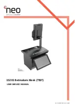
15201 Betmakers Kiosk (TSST)


USER SERVICE MANUAL


Содержание 15201

Страница 1: ...15201 ML002 REV05 ECN 5847 15201 Betmakers Kiosk TSST USER SERVICE MANUAL...

Страница 2: ...N A DRAFT COPY KR 02 24 11 2021 5790 UPDATED SERVICE MANUAL L DICKSON 03 03 12 2021 5790 AMENDED SERVICE MANUAL FORMAT CLARIFICATION OF STEPS L DICKSON 04 15 12 2021 5790 ADDITION OF FCC NOTATION L D...

Страница 3: ...y Notices 6 Electrostatic Discharge ESD 6 2 Product Description 7 2 1 Physical Specifications Operating Environment 7 2 1 1 Mechanical 7 2 1 2 Environmental 7 2 1 3 Electrical 7 2 2 Power Connection C...

Страница 4: ...nd or changes in the product and or programme described in this publication without advance notice if Neo Products believes it is appropriate to do so Changes will be incorporated in new editions of t...

Страница 5: ...connect signal cables Never turn ON any equipment when there is evidence of fire water or structural damage Sharp edges corners and joints may be present in and around the system Use care when handlin...

Страница 6: ...hority to operate the equipment Federal Communications Commission Statement FCC Note This equipment has been tested and found to comply with the limits for a Class A digital device pursuant to part 15...

Страница 7: ...ectrical Mains Input Mains Input to 100 240V AC 400W 50 60Hz 4A Maximum A dedicated circuit for each Kiosk is not required A grounded power outlet with IEC cable for connection to the Kiosk Pedestal i...

Страница 8: ...utton on the side of the Top Lid to allow the Top Lid to lift open STEP 3 Remove the paper roll spindle Push the paper roll spindle inwards to allow it to slide upwards and out of the printer swing br...

Страница 9: ...STEP 6 Remove retain 3x Pan Head Screws fastening the Printer Module to the green tray 7 STEP 7 Remove 3x plugs from rear of the Printer Module CAUTION Servicing of this product or unit is to be perf...

Страница 10: ...en tray STEP 1 To remove the MSR Module press the button on the side of the Top Lid to allow the Top Lid to lift open STEP 3 Remove the MSR Module from the peripheral tray CAUTION Servicing of this pr...

Страница 11: ...ow Steps 1 to 5 in reverse STEP 5 Remove retain 4x Pan Head Screws fastening the MSR Module to the green tray STEP 4 Tilt the MSR Module to access the Power connector located behind the MSR Module Unp...

Страница 12: ...the BNA Module press the button on the side of the Top Lid to allow the Top Lid to lift open STEP 3 Swing open the BNA Lock Bracket STEP 4 Pull the yellow handle of the BNA Cash Box from the BNA Brack...

Страница 13: ...ntly guiding the small tabs on the Module past the slots on the BNA Bracket 5 Chapter 5 BNA Module STEP 6 Remove retain 2x Pan Head Screws fastening the BNA Mount Bracket to the base 6 STEP 7 Re close...

Страница 14: ...connected to the USB Hub Replacing the BNA Module 9 10 STEP 11 Remove 2x plugs from the USB Hub To re install the replacement BNA Module follow Steps 1 to 11 in reverse Chapter 5 BNA Module STEP 9 Li...

Страница 15: ...to 3 in reverse STEP 3 Hold the Bill Validation Module and gently lift the steel rod upwards to disengage remove from the BNA Bracket Note Remove the Bill Validation Module by guiding the small tabs...

Страница 16: ...rame STEP 4 The PC Tray travel is limited by the Main Loom length Partially pull out the PC Tray ensuring that there is suitable support under the Tray prior to full removal 4 Replacing the PC 1 3 2 S...

Страница 17: ...Sensor wires To re install the replacement PC follow Steps 1 to 7 in reverse Replacing the PC 5 6 STEP 7 Remove retain 4x Nuts fastening the PC to the base Chapter 7 PC CAUTION Servicing of this prod...

Страница 18: ...TEP 1 Re orientate the Teller LCD Screen upwards to the full horizontal position STEP 4 Swing open the Bet Slip Reader Swing Mount CAUTION Servicing of this product or unit is to be performed by train...

Страница 19: ...reen Remove retain 2x Bush Hinge 2x M6 Pan Head Screws To re install the replacement Teller LCD Screen follow Steps 1 to 7 in reverse STEP 6 Un feed the Teller LCD Screen loom from USB Hub through the...

Страница 20: ...5mm Allen Key supplied Tighten once correct angle is achieved 1 STEP 1 Small adjustments can be achieved for the position of the LCD Customer Screen for angle height 2 STEP 2 LCD Customer Screen adju...

Страница 21: ...e Customer LCD Screen Chapter 9 Customer LCD SCREEN 5 STEP 5 Recheck Customer Screen angle height If further adjustment is required repeat Steps 3 to 5 CAUTION Servicing of this product or unit is to...

Страница 22: ...C Reader STEP 3 Remove the NFC Reader USB con nector from the applicable USB Port 1 STEP 1 To remove the NFC Reader press the button on the side of the Top Lid to allow the Top Lid to lift open 2 STEP...

Страница 23: ...e replacement Customer LCD Screen follow Steps 1 to 3 in reverse STEP 1 To remove the Customer LCD Screen press the button on the side of the Top Lid to allow the Top Lid to lift open 1 STEP 3 Loosen...

Страница 24: ...ity Sensor from the Top Lid Remove replace the Proximity Sensor To re install the replacement Proximity Sensor follow Steps 1 to 4 in reverse 4 Replacing the Proximity Sensor 1 3 2 STEP 2 The Proximit...

Страница 25: ...15201 ML002 REV05 ECN 5847 Page 25 CAUTION Servicing of this product or unit is to be performed by trained service personnel only...

Отзывы: