Navman G-PILOT 3380, Руководство по установке
"Navman G-PILOT 3380" - современная автоматическая система управления курсом для яхт и катеров. Для установки и настройки прибора необходимо загрузить бесплатное руководство по установке с официального сайта производителя. Загрузите его с manualshive.com и наслаждайтесь простотой использования этого продукта.
Поделиться
Скачать


Отзывы:
Нет отзывов
Похожие инструкции для G-PILOT 3380

PT500
Бренд: YOKOGAWA Страницы: 132

Reactor 40 Kicker
Бренд: Garmin Страницы: 28
GHC 10
Бренд: Garmin Страницы: 26
ST1000+
Бренд: Raymarine Страницы: 76
System 55X
Бренд: S-TEC Страницы: 24
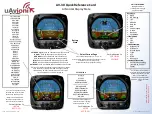
AV-30
Бренд: uAvionix Страницы: 4
GHP 20 Marine Autopilot System for...
Бренд: Garmin Страницы: 20

AUTOPILOT / TRIM
Бренд: Xflighttech Страницы: 44
AP50
Бренд: Simrad Страницы: 142
GHP 12 Autopilot System
Бренд: Garmin Страницы: 32
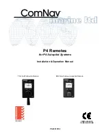
P4 Remotes Series
Бренд: ComNav Страницы: 40
Autohelm ST1000
Бренд: AUTOHELM Страницы: 35

SAS-70
Бренд: Samyung ENC Страницы: 33
AP56
Бренд: TMQ Страницы: 24

KFC225
Бренд: BENDIXKing Страницы: 25
Verado
Бренд: Raymarine Страницы: 72
Ace One
Бренд: dji Страницы: 44

SmartPilot X-5 ST6002 Controller
Бренд: Raymarine Страницы: 2


