


Summary of Contents for FISH 4500/4600
Page 33: ......
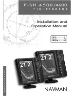
The Navman FISH 4500/4600 is a feature-packed fishfinder that promises exceptional performance on fishing trips. To ensure hassle-free setup and seamless operation, we offer a comprehensive "Installation and Operation Manual" that you can download for free from our website. Get yours now at manualshive.com and maximize your fishing experience.
Page 33: ......