NATURA NWSB SERIES 3, Installation And Maintenance Instruction Manual
The NATURA NWSB SERIES 3 is a high-quality product designed for easy installation and minimal maintenance. For detailed instructions on how to set up and care for your device, download the free Installation And Maintenance Instruction Manual from manualshive.com. Ensure optimal performance and longevity with this essential manual.
Share
Download


Reviews:
No comments
Related manuals for NWSB SERIES 3

COT2000 Series
Brand: Hamilton Beach Pages: 8

SmartServe BIC2000
Brand: Hamilton Beach Commercial Pages: 28

OneShot Foam
Brand: Rubbermaid Pages: 4

KAWD100FBK
Brand: nedis Pages: 72

Aquakinetic Q237
Brand: Kinetico Pages: 32

WL Max
Brand: WaterLogic Pages: 19

HVR Series
Brand: Halsey Taylor Pages: 7

150L SunStream Indirect
Brand: SUNSCAN Pages: 24

MVU TOWER
Brand: lancer Pages: 24

GPVX 75L Series
Brand: A.O. Smith Pages: 52

AST1257TMP-960
Brand: IBC Water Pages: 33

Blue Lake L
Brand: Osmofilter Pages: 38

OKCE 100 NTR/2,2kW
Brand: Dražice Pages: 11

SNE 5 t ECO
Brand: STIEBEL ELTRON Pages: 20

943
Brand: DIMA Pages: 2

WV4262B
Brand: Honeywell Pages: 12

VE300S
Brand: Honeywell Pages: 28
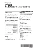
WT8840
Brand: Honeywell Pages: 8


