Narco Avionics MK12D TSO, Installation Manual
The Narco Avionics MK12D TSO is a top-of-the-line avionics system. Ensure smooth installation with the comprehensive and user-friendly Installation Manual. Download it for free from manualshive.com. This manual provides step-by-step instructions and detailed illustrations, allowing you to maximize the capabilities of this exceptional product.
Share
Download


Reviews:
No comments
Related manuals for MK12D TSO

TD-H6
Brand: TIDRADIO Pages: 11
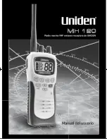
MH120
Brand: Uniden Pages: 32

SR-1
Brand: Ramsey Electronics Pages: 22

Gemini PD
Brand: Dataradio Pages: 31

CR-26 DABPLUS
Brand: Denver Pages: 27

RCR-22
Brand: Sangean Pages: 78

Siesta Rise ZDD055200
Brand: PURE Pages: 24

LBI-31693B
Brand: Com-Net Ericsson Pages: 20

PL-210
Brand: Tecsun Pages: 24

RCR-2
Brand: Sangean Pages: 18

GTX 3X5 Series
Brand: Garmin Pages: 174

VX-6000
Brand: Vertex Standard Pages: 31

AE1000
Brand: Philips Pages: 2

AE 6570
Brand: Philips Pages: 2

23RL475
Brand: Philips Pages: 4

RF-SW70
Brand: Panasonic Pages: 2

RF-521
Brand: Panasonic Pages: 1
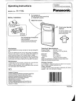
R-1105
Brand: Panasonic Pages: 1


