background image

SCHEDULE TYPE:

PROJECT:

ENGINEER:

CONTRACTOR:

DATE

B SERIES

SUPERSEDES DRAWING NO.

5 - 7 - 12

1200

3 - 21 - 11

1210SS-1

STAINLESS STEEL SMOKE DAMPER 

AIRFOIL BLADE • HIGH PERFORMANCE 
ULTRA-LOW LEAKAGE • LOW PRESSURE DROP

MODELS: 1210SS AND 1211SS (TYPE A)

Nailor Industries Inc. reserves the right to change any information concerning product or pricing without notice.

For installation instructions, see IOM-SDINST.

Dimensions are in inches (mm).

The 1210SS Series dampers are ideal for high humidity, mildly
corrosive or, with optional Type 316 construction, more severe
environments where building codes require a leakage rated smoke
damper as part of a static smoke control or dynamic smoke
management system. 

The 1210SS Series has been especially designed and tested to
offer premium performance. The 1210SS Series provides the
lowest leakage class available and is qualified for vertical or
horizontal installation with airflow in either direction. Airfoil blade
design and elimination of blade sills, top and bottom, provide
lowest pressure drop. Unique inter-locking double skin blade
design eliminates combustible blade seals and provides flame and
smoke seal under fire conditions. 

STANDARD SPECIFICATION:

Frame:

5" x 7/8" x 16 ga. (127 x 22 x 1.6) stainless steel 
hat channel.

Blades:

14 ga. (2.0) equivalent stainless steel formed airfoil on 
5 1/2" (140) centers. Opposed action. 

Linkage:

Concealed in frame. 12 ga. (2.7) stainless steel.

Bearings:

1/ 2" (13) dia. sintered stainless steel.

Axles:

1/ 2" (13) dia. stainless steel double bolted to blades.

Jackshaft:

1/2" (13) dia. stainless steel.

Jamb Seals:

Cambered stainless steel.

Sizes (Damper W x H):

Note:

Dampers with duct heights less than 8" (203) require a Type ‘B’

sleeve enclosure (Model 1212SS). Units less than 8" (203) in width only, or
in both width and height, require a Type ‘C’ enclosure (Model 1213SS).

BASE MODEL SELECTION:

1210SS

With side actuator mounting plate

1211SS 

Standard factory sleeve (caulked to UL requirements)
16" long x 20 ga. (406 x 1.0) (18 ga. for dampers over 
84" [2134] in width). 

1211SS

Non-standard sleeve.
Specify  _______  length  _____  ga.

Available up to 36" (914) in length and 10 through
20 ga. (3.5 through 1.0).
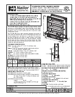
7 3/4"

(197) MAX.

10 3/4"

(273) MAX.

JACKSHAFT

3 15/16"

(100)

CONSTRUCTION TYPE:

304

Type 304 Stainless Steel construction (Standard).

316 

Type 316 Stainless Steel construction (Optional).

LEAKAGE CLASS/ELEVATED TEMPERATURE:

I

II      @ 250°F

DYNAMIC VELOCITY/PRESSURE RATING:

24  

2000 fpm @ 4" w.g.

ACTUATOR SELECTION:

Electric

Pneumatic

ACTUATOR LOCATION:

External

(std.)

Internal

(in the airstream)

ACTUATOR FAIL POSITION:

Normally Closed

(std.)

Normally Open

OPTIONS:

MLS-300

Position indicator switch pack

CCW

TO

OPEN

5"

(127)

W = NOMINAL

 DUCT

 SIZE - 1/4"

 (6)

H = NOMINAL

 DUCT

 SIZE - 1/4" (6)

QUALIFICATIONS:

• UL 555S CLASSIFIED SMOKE DAMPER (File # R9492)

Leakage Class I or II at 250°F elevated temperature.

• Meets NFPA 90A, 92A, 92B, 101 and 105 as well as IBC and 

NBC (Canada) Building Code requirements.

• California State Fire Marshal Listing No. 03230-0935:107.
• City of New York MEA# 366-03-M.

• Maximum velocity: 2000 fpm@ 4" w.g.

Velocity/

Pressure

Rating

Elevated

Temp.

°F

Minimum

Maximum

Single Section

Single Section

Multiple Section

Vertical/Horizontal Vertical/Horizontal Vertical/Horizontal

24

250

8" x 8" (203 x 203)

36" x 48"

(914 x 1219)

144" x 96"

(3658 x 2438)

Summary of Contents for 1210SS

Page 1: ...es Jackshaft 1 2 13 dia stainless steel Jamb Seals Cambered stainless steel Sizes Damper W x H Note Dampers with duct heights less than 8 203 require a Type B sleeve enclosure Model 1212SS Units less than 8 203 in width only or in both width and height require a Type C enclosure Model 1213SS BASE MODEL SELECTION 1210SS With side actuator mounting plate 1211SS Standard factory sleeve caulked to UL ...

Page 2: ... bolted to blades Jackshaft 1 2 13 dia stainless steel Jamb Seals Cambered stainless steel Sizes Duct W x H Note Duct sizes less than 8 203 in width only or in both width and height require a Type C enclosure Model 1213SS SLEEVE ENCLOSURE SELECTION 1212SS Standard factory sleeve caulked to UL requirements 16 long x 20 ga 406 x 1 0 18 ga for dampers over 84 2134 in width 1212SS Non standard sleeve ...

Page 3: ...tainless steel double bolted to blades Jackshaft 1 2 13 dia stainless steel Jamb Seals Cambered stainless steel Sizes Duct Diameter SLEEVE ENCLOSURE SELECTION 1213SS Standard factory sleeve caulked to UL requirements 16 long x 20 ga 406 x 1 0 18 ga for dampers over 84 2134 in width 1213SS Non standard sleeve Specify _______ length _____ ga Available up to 36 914 in length and 10 through 20 ga 3 5 ...

Page 4: ... Axles 1 2 13 dia stainless steel double bolted to blades Jackshaft 1 2 13 dia stainless steel Jamb Seals Cambered stainless steel Sizes Duct W x H SLEEVE ENCLOSURE SELECTION 1213SS Standard factory sleeve caulked to UL requirements 16 long x 20 ga 406 x 1 0 18 ga for dampers over 84 2134 in width 1213SS Non standard sleeve Specify _______ length _____ ga Available up to 36 914 in length and 10 th...

Page 5: ...ctric Resettable Link Damper Test Switch ERL Reset Temp 165 F 212 F 250 F 350 F ERL DTS 12 19 DTS Push To Test Press and hold down Momentary push button until damper has fully cycled The electric resettable link is manual reset type L2 L1 BLK BLK ELECTRIC ACTUATOR OR EP SWITCH WHT MOUNTED ON DAMPER FACTORY WIRING TERMINATES AT SPLICE POINTS INDICATED INSIDE 4 x 4 ELECTRICAL BOX HEAT SENSOR ERL M B...

Page 6: ...S 12 19 ERL DTS Combination Fire Smoke Damper DTO DTS Combination Fire Smoke Damper DTS Smoke Damper Model Series Open OP Closed CL MSXX04 Yellow Yellow Blue Blue MSXX20 Yellow Yellow Blue Blue Honeywell Actuator Aux Switch Wiring Connections WHT BLK BLK BLK BLK RED L2 L1 CLOSED RED LIGHT OPEN GREEN LIGHT CONTROL SWITCH NORMAL MS2 DAMPER CLOSED LOWER MICROSWITCH BLU BLU YEL YEL MS1 DAMPER OPEN UPP...

Page 7: ...CT SIZE 1 4 6 NOTE Smoke Dampers shall be installed in accordance with NFPA 90A latest edition and Nailor installation instructions see IOM SDINST Dampers must be installed within 24 610 of the smoke barrier to conform with installation requirements SMP SIDE ACTUATOR MOUNTING PLATE JACKSHAFT DRIVE MODELS 9 229 WIDTH NOM DUCT SIZE 1 8 3 HEIGHT NOM DUCT SIZE 1 4 6 5 127 1 25 16 406 STD 12 305 MIN W ...

Page 8: ...Reversible mounting facilitates use in either clockwise cw or counterclockwise ccw spring rotation Integral spring return ensures level of return torque Stainless steel internal spring Fifteen second spring return timing No special cycling required during long term holding See Operation section No audible noise during holding Patent pending design eliminates need for limit switches to reduce power...

Page 9: ...ntrol system Refer to National Fire Protection Association NFPA National Fire Codes NFPA90A NFPA92A and NFPA92B for your application NFPA recommends periodic examination of each fire smoke damper semi annually or annually to ensure proper performance Mounting Self centering shaft adapter Round Damper Shafts 0 5 to 1 06 in Square Damper Shafts 1 2 to 3 4 in Actuator can be mounted with shaft in any...

Page 10: ...ion Control Reversible Mount Spring Return 20 175 lb in 20 Nm F Fire and Smoke US 1 No Feedback 0 No Auxiliary Switches 2 Two Auxiliary Switches XX System Controlled Numbers M S 41 20 F 1 2 XX Table 3 Actuator Selection S20 Series S Fail Safe Function Spring Return 20 20 Nm 175 lb in 24 24 Vac 2 position Control Reversible Mount Spring Return 230 230 Vac 2 position Control Reversible Mount Spring ...

Page 11: ... housing can damage actuator Mount actuator to allow it to float along its vertical axis Preparation Before mounting the actuator onto the damper shaft determine the Damper valve opening direction for correct spring return rotation The actuator can be mounted to provide clockwise or counterclockwise spring return Damper shaft size see Specifications section Determine Appropriate Mounting Orientati...

Page 12: ... on damper housing 3 Remove actuator and mounting bracket 4 Drill or center punch holes for mounting screws or use no 10 self tapping sheet metal screws NOTE If necessary use a field fabricated steel base plate secured with sheet metal screws 5 Turn damper blades to desired normal closed position 6 Place actuator and mounting bracket back into position and secure bracket to damper box with sheet m...

Page 13: ...equipment circuitry Disconnect power supply before installation CAUTION Electrical Shock or Equipment Damage Hazard Disconnect all power supplies before installation Motors with auxiliary switches can have more than one disconnect IMPORTANT 1 All wiring must comply with local electrical codes ordinances and regulations 2 Voltage and frequency of transformer used with MS8120F S and S2024 F must cor...

Page 14: ...al 230 Vac wiring S20 Series M20678A BLUE BROWN 230 VAC S2024 F SW2 MS8120S L1 L2 BLACK BLUE BLACK RED BLACK YELLOW GRAY RED GRAY BLUE GRAY YELLOW 85 AUXILIARY SWITCH 7 AUXILIARY SWITCH M20680A BLUE BROWN 230 VAC S20230 F SW2 MS4620S L1 L2 BLACK BLUE BLACK RED BLACK YELLOW GRAY RED GRAY BLUE GRAY YELLOW 7 AUXILIARY SWITCH 85 AUXILIARY SWITCH ...

Page 15: ...ould drive the damper 3 If the actuator does not run remove power for at least two seconds 4 If the actuator spring returns allow it to close entirely then return to step 2 5 If the actuator does not spring return verify that the actuator is properly installed See Installation section 6 If the actuator is correctly installed but neither runs nor spring returns replace the actuator MS4620F S20230 F...

Page 16: ...ation DK Installasjonsinstruks S Installations Instrukioner I Istruzioni per I Installazione N Installationsinstrukioner E Instrucciones de montage A A1 A4 A2 A5 A3 A6 M20730B a b 10 mm M20729A a b d c b M20728A b a M20727A M20726A ASSEMBLY EINBAU MONTAGE MONTAGGIO MONTAGE MONTERE MONTERING ASENTAMINEN MONTERA MONTAJE D F I NL DK N FIN S E 24 VAC 120 VAC 230 VAC M12030 a b ...

Page 17: ...TING TWO POSITION ACTUATORS 63 2584 10 10 B B1 B4 B3 B2 M20735B M20734A a M20733B M20732A a b M20731B 24 VAC 120 VAC 230 VAC DISASSEMBLY AUSBAU DÉMONTAGE SMONTAGGIO DEMONTAGE AFMONTERE DEMONTERE PURKAMINEN NEDMONTERA DESMONTAJE D F I NL DK N FIN S E ...

Page 18: ...MS4120F MS4620F MS8120F S2024 F S20230 F FAST ACTING TWO POSITION ACTUATORS 11 63 2584 10 ...

Page 19: ...Douglas Drive North Golden Valley MN 55422 customer honeywell com U S Registered Trademark 2012 Honeywell International Inc 63 2584 10 M S Rev 03 12 Printed in United States Teflon is a registered trademark of the E I du Pont de Nemours and Company National Fire Codes is a registered trademark of the National Fire Protection Association NFPA ...

Page 20: ...n either clockwise cw or counterclockwise ccw spring rotation Integral spring return ensures level of return torque Fifteen second spring return timing No special cycling required during long term holding See Operation section No audible noise during holding Patent pending design eliminates need for limit switches to reduce power consumption Models available for 24 120 and 230 Vac Ninety five degr...

Page 21: ...or coded leads Mounting Round 1 2 inch shaft adapter with 1 4 inch set screws Threads 20 UNC 2A Material Alloy Steel hardened to HRC 45 53 Thread Lock Nylon Patch IMPORTANT Honeywell does not recommend using linkages with these actuators because side loading of the output hub reduces actuator life Temperature Ratings Ambient 0 F to 130 F 18 C to 55 C Shipping and Storage 40 F to 140 F 40 C to 60 C...

Page 22: ...nal codes for periodic testing of the entire smoke control sys tem Refer to National Fire Protection Association NFPA National Fire Codes NFPA90A NFPA92A and NFPA92B for your application NFPA recommends periodic examination of each fire smoke damper semi annually or annually to ensure proper perfor mance Design Life at Rated Voltage 30 000 full stroke cycles Approvals See Table 3 Environmental Pro...

Page 23: ... Location and Mounting The actuators are designed to open a damper by driving the damper shaft in either clockwise or counterclockwise direction The actuator housing has two slots on the bottom that with a 205649 Mounting Bracket secure it flush to a damper box see Fig 2 When mounted correctly these slots allow the actuator to float without rotating relative to the damper shaft CAUTION Equipment D...

Page 24: ...ing min imum 100 lb in maximum 130 lb in torque Use 1 4 in wrench see Specifications for details to tighten set screws Wiring See Fig 3 through 5 for typical wiring diagrams WARNING Electrical Power Hazard Line voltage can cause death or serious injury and short equipment circuitry Disconnect power supply before installation CAUTION Electrical Shock or Equipment Damage Hazard Low voltage can shock...

Page 25: ...rsion to 350 F 176 C CHECKOUT MS4104F MS4109F 120 Vac model 1 Check damper position 2 Connect 120 Vac to the black and white leadwires to drive the damper to the open position The actuator should drive the damper 3 If the actuator does not spring return verify that the actu ator is properly installed See Installation section 4 If the actuator is correctly installed but neither runs nor spring retu...

Page 26: ...7 63 2740 05 ...

Page 27: ...rol Solutions Honeywell International Inc 1985 Douglas Drive North Golden Valley MN 55422 customer honeywell com U S Registered Trademark 2013 Honeywell International Inc 63 2740 05 M S Rev 12 13 Printed in United States ...

Page 28: ...limiting property damage including damage to the HVAC system itself Refer to NFPA Standards 72 90A and 92 to determine when and where duct smoke detectors are required The DSD NF detector can be factory installed to side of sleeve on Nailor Model Series 1210 1260 1280 1220 and 1270 A minimum airflow velocity of 100 fpm 0 5 m s is required for Model DSD LF OPERATION Upon detection of smoke the smok...

Page 29: ...e from spreading within the HVAC system is vital to preventing injury as well as limiting property damage including damage to the HVAC system itself Refer to NFPA Standards 72 90A and 92 to determine when and where duct smoke detectors are required The DSD NF detector features a low profile design for optimum pressure drop and will operate with airflow in either direction It can be factory install...

Page 30: ...pply must be used Operation Mounting of the actuator to the damper axle shaft or jackshaft is via a cold weld clamp Teeth in the clamp and V bolt dig into the metal of both solid and hollow shafts maintaining a perfect connection The specially designed clamp will not crush hollow shafts The bottom end of the actuator is held by an anti rotation strap or by a stud provided by the damper manufacture...

Page 31: ...ode requirements Wiring Diagrams APPLICATION NOTES Provide overload protection and disconnect as required 45 Actuators may be powered in parallel Power consumption must be observed 75 Ground present on some models 45 2 Hot 1 Neutral 3 Ground 1 N White L1 Black 120 VAC Detector or relay F S Damper 2 1 HOT 165 F To alarm system Manual reset Actuator N L2 or COM Typical containment damper control wir...

Page 32: ...e used Operation Mounting of the actuator to the damper axle shaft or jackshaft is via a cold weld clamp Teeth in the clamp and V bolt dig into the metal of both solid and hollow shafts maintaining a perfect connection The specially designed clamp will not crush hollow shafts The bottom end of the actuator is held by an anti rotation strap or by a stud provided by the damper manufacturer The actua...

Page 33: ... code requirements Wiring Diagrams APPLICATION NOTES Provide overload protection and disconnect as required 45 Actuators may be powered in parallel Power consumption must be observed 75 Ground present on some models N Blue L1 Brown 1 N L2 2 Hot 3 Ground 45 1 230 VAC Detector or relay F S Damper 2 1 HOT 165 F To alarm system Manual reset Actuator N L2 or COM Typical containment damper control wirin...

Page 34: ...ulated power supply must be used Operation Mounting of the actuator to the damper axle shaft or jackshaft is via a cold weld clamp Teeth in the clamp and V bolt dig into the metal of both solid and hollow shafts maintaining a perfect connection The specially designed clamp will not crush hollow shafts The bottom end of the actuator is held by an anti rotation strap or by a stud provided by the dam...

Page 35: ...s will be provided per code requirements Wiring Diagrams APPLICATION NOTES Provide overload protection and disconnect as required 45 Actuators may be powered in parallel Power consumption must be observed 75 Ground present on some models 24 VAC Detector or relay F S Damper 2 1 HOT 165 F To alarm system Manual reset Actuator N L2 or COM Typical containment damper control wiring Detector or relay F ...

Page 36: ...e metal of both solid and hollow shafts maintaining a perfect connection The specially designed clamp will not crush hollow shafts The bottom end of the actuator is held by an anti rotation strap or by a stud provided by the damper manufacturer The actuator is mounted in its fail safe position with the damper blade s closed Upon applying power the actuator drives the damper to the open position Th...

Page 37: ... Belimo FSTF FSLF FSNF or FSAF actuators All substitutions must be approved before submission of bid Damper and actuator shall have UL 555S Listing for 250 F 350 F Actuator shall have been tested to UL 2043 per requirements of IMC 602 2 and NEC 300 22 c Where position indication is required S models with auxiliary switches or damper blade switches will be provided per code requirements Wiring Diag...

Page 38: ...ction The specially designed clamp will not crush hollow shafts The bottom end of the actuator is held by an anti rotation strap or by a stud provided by the damper manufacturer The actuator is mounted in its fail safe position with the damper blade s closed Upon applying power the actuator drives the damper to the open position The internal spring is tensioned at the same time If the power supply...

Page 39: ... shall be provided with Belimo FSTF FSLF FSNF or FSAF actuators All substitutions must be approved before submission of bid Damper and actuator shall have UL 555S Listing for 250 F 350 F Actuator shall have been tested to UL 2043 per requirements of IMC 602 2 and NEC 300 22 c Where position indication is required S models with auxiliary switches or damper blade switches will be provided per code r...

Page 40: ...e clamp and V bolt dig into the metal of both solid and hollow shafts maintaining a perfect connection The specially designed clamp will not crush hollow shafts The bottom end of the actuator is held by an anti rotation strap or by a stud provided by the damper manufacturer The actuator is mounted in its fail safe position with the damper blade s closed Upon applying power the actuator drives the ...

Page 41: ...tuators All substitutions must be approved before submission of bid Damper and actuator shall have UL 555S Listing for 250 F 350 F Actuator shall have been tested to UL 2043 per requirements of IMC 602 2 and NEC 300 22 c Where position indication is required S models with auxiliary switches or damper blade switches will be provided per code requirements Wiring Diagrams INSTALLATION NOTES Provide o...

Page 42: ...0 Vdc Standard Mounting MS1 is damper open signal MS2 is damper closed signal Non Standard Mounting Important Installer must double check continuity of MS1 and MS2 before wiring to determine which switch signals the damper s open or closed position EXTERNAL RIGHT HAND MOUNTING FRONT VIEW LESS COVER COVER A A 2 7 8 73 3 76 4 1 8 105 MS 2 MS 1 BLUE YELLOW SECTION A A JACKSHAFT DRIVESHAFT EXTENSION C...

Page 43: ... MS4604F1210 MS4609F1210 Ratings maximum load 120 VAC 24 VDC 3A resistive Settings fixed 7 nominal stroke 85 nominal stroke Model MS8104F1210 MS8109F1210 Ratings maximum load 24 VAC DC 3A resistive Settings fixed 7 nominal stroke 85 nominal stroke Model MS4120F1204 MS4620F1203 MS8120F1200 Ratings maximum load 250 VAC 5A resistive Settings fixed 7 nominal stroke 85 nominal stroke Belimo Model FSTF1...

Reviews: