background image


OPERATING 

INSTRUCTION  

744Р-0000010  


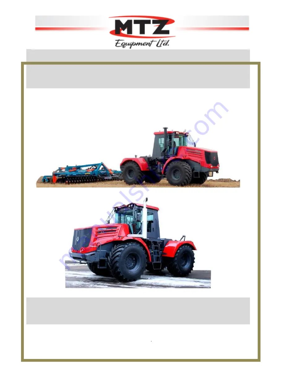
MTZ-KIROVETS tractors  K-744R1, K-744R2 


     K-744R3, K-744R4


Head Office:

  3-1136 Centre St. Ste 124, Thornhill, ON, L4J 3M8,  Canada      

Warehouse:

  2682 Highway 34, Hawkesbury,  Ontario.  K6A 2R2  Canada   

Tel: 

1-855-2GO-4MTZ  (1-855-246-4689)  

Fax: 

 1-647 933-9066  

 E-mail:   

[email protected]

   Web

www.mtzequipment.com 


Summary of Contents for K-744R1

Page 1: ...4R1 K 744R2 K 744R3 K 744R4 Head Office 3 1136 Centre St Ste 124 Thornhill ON L4J 3M8 Canada Warehouse 2682 Highway 34 Hawkesbury Ontario K6A 2R2 Canada Tel 1 855 2GO 4MTZ 1 855 246 4689 Fax 1 647 933...

Page 2: ...MTZ KIROVETS tractors K 744R1 K 744R2 K 744R3 K 744R4 2...

Page 3: ...the design which are not reflected herein ABBREVIATIONS GB gearbox PW paintwork paint and lacquer coating PTO power take off ET electric torch PDR pump drive reducer SPTA spare parts tools and access...

Page 4: ...EL FOR K 744R2 K 744R3 K 744R4 TRACTORS OF THE PREMIUM DESIGN VERSION 53 4 5 TRACTOR SYSTEM CONTROL 58 4 6 SWITCH BLOCK ON THE STEERING COLUMN 61 4 7 SWITCHES ON THE OVERHEAD PANEL IN THE CABIN 62 4 8...

Page 5: ...STORAGE 121 7 4 LUBRICATION TABLE 123 7 5 CONTENTS AND PROCEDURE OF MAINTENANCE OPERATIONS 129 7 5 1 Change of oil in the engine 129 7 5 2 Adjustment of cylinder valves on 8481 engine 129 7 5 3 Air c...

Page 6: ...APPENDIX 9 List of electrical equipment elements to the electrical diagram of the K 744R1 Standard tractor 176 APPENDIX 9A List of electrical equipment elements to the electrical diagram of the K 744...

Page 7: ...IBITED to openplugs of the tank filler and expansion tank or unscrew the steam air valve at the cooling fluid temperature over 70 IT IS PROHIBITED to work on the tractor with faulty steering control b...

Page 8: ...nge lever and avoid sharp turns and passing obstacles In crossing dams dikes and bridges make sure of the possibility of driving and use only low gears Crossing trenches hillocks and other obstacles w...

Page 9: ...battery front axle is engaged deactivated front and rear axles are engaged activated sound signal fan smooth regulation by rotation front wiper washer smooth regulation by movement rear window washer...

Page 10: ...in rear brake circuit power take off shaft engaged abnormal operation of any system power take off shaft disengaged lifting of mounted implement slower lowering of mounted implement faster floating po...

Page 11: ...owing sowing scuffing disk harrowing deep ploughing tilting the soil without or before ploughing snow capture and other kinds of work In addition the tractors can effectively be used in transport oper...

Page 12: ...soils 1 4 2 Mill for pastures 1 2 9 Ripper 1 3 5 Subsurface plough 1 4 Subsurface plough fertiliser distributor 1 1 4 Stone extracting machine 1 227 Snow breaker of mill type 1 11 Pushing drag harrow...

Page 13: ...lanter instead of 3 6 1 Seed fertiliser press non coupling planter instead of 3 6 1 Seed fertiliser row drill tusk type planter instead of 3 6 1 Seed fertiliser broad catching planter 1 Hitch iron See...

Page 14: ...Reclamation on tractor failures in case of its hooking up with agricultural machines and implements which are not agreed upon with Peterburgskytraktorny zavod JSC will not be accepted for review The...

Page 15: ...cal equipment of tractors is fitted out with preparation for installation of the Glonass data acquisition and storage system which is located under the instrument panel When ordering tractors with the...

Page 16: ...by making tractor turns from one extreme position to the other with holding at the stop during 3 5 seconds each time or by forced lowering of the mounted implement ATTENTION IT IS PROHIBITED to fill...

Page 17: ...telescopic hydraulic shock absorbers The rear axles of all tractors are fastened rigidly to the frame The service brakes are dry of block type with a separate pneumatic drive to the front and rear wh...

Page 18: ...ocated in the steering column base being pressed The adjustment of the steering wheel over height at the flywheel located in the steering wheel centre being turned at 2 3 revolutions The pneumatic sys...

Page 19: ...in the pneumatic system within specified limits as well as serves for protection against overload and contamination When the brake pedal is pressed air will get through the brake valve into the servi...

Page 20: ...ve with pedal 5 8 reverse action braking valve with manual control 6 acceleration valve 7 trailer brake control valve with single wire drive 9 reference output valve 10 disconnecting valve 11 connecti...

Page 21: ...ote cable operated control is installed on the tractors in the hydraulic system of working equipment out of them four sections levers 2 3 4 5 are designed for connection to external hydraulic lines Al...

Page 22: ...ydraulic lines from handles 2 3 4 5 with the same name In order to reduce losses in the hydraulic system and avoid its overheating during operations with planters equipped by a hydraulic motor of the...

Page 23: ...744R4 tractors 23 Installation of free drain and drainage paths Angle XEWAD12lz3 Union XGE12M16ZiWDPz3 Free drain Hose 2SN20 DKOL90 DKOL 3200 Clamp 30 20 M8 Coupling CPV082 1815F Coupling CPV162 302F...

Page 24: ...gle XEWAD12Lz3 union XGE12M16ZLWDPz3 hose 2SN 10 DKOL DKOL L 3 700 and coupling CPV082 1815F The installation of the drainage set shall be performed as follows dismantle the plug M16 on the hydraulic...

Page 25: ...10 hours of tractor operation the subsequent inspections shall be carried out once in every 6 months or upon tractor commissioning after long term storage ATTENTION THE INSPECTION SHALL BE PERFORMED B...

Page 26: ...e position during several seconds In case of tractor configuration including EHR system position regulation of the suspension axis EHR control unit 1 lifting lowering handle 2 switch for blocking the...

Page 27: ...is necessary to do the following Holding the boot with one hand shift the latch to the right up to the click with the other hand without any special effort The lock will get unblocked and the boot wi...

Page 28: ...to the chest level it is necessary to re catch the knob and perform closing of the boot until the lock operates Safety measures In order to observe safety measures with regard to prevention of spontan...

Page 29: ...apacity no more than 220 167 213 157 220 162 205 151 213 157 205 151 213 157 205 151 at the operating capacity no more than 237 174 240 177 213 157 230 170 213 157 230 170 213 157 at the maximum capac...

Page 30: ...le 7 516 8 046 8 470 8 010 10 500 9 900 10 500 9 900 rear axle 6 854 7 210 9 100 9 300 9 100 9 300 The largest pressure from mean conventional pressure values for driving machines kPa kgf cm 2 no more...

Page 31: ...s at the wheel level 2 865 2 875 width on doubled wheels at the wheel level 2 865 3 865 height 3 846 3 876 Tractor braking distance at the motion speed of 8 3 m s 30 km h m no more than 13 Static late...

Page 32: ...completed and serviceable A first aid kit stocked in accordance with applicable regulatory documents shall be installed and fixed in the tractor cabin If it is required to use cabin windows as an esca...

Page 33: ...vance of all occupational and industrial safety regulations and fire safety regulations 3 3 Safety measures during tractor operation Before starting the engine the change gear lever and thechange mode...

Page 34: ...and alarm signaling All tractor control levers shall admit fixing in the corresponding positions The tractor brakes shall be in good working condition During braking of the tractor travelling over dry...

Page 35: ...the tractor and mounting of agricultural machines and implements on the tractor shall be carried out by persons operating such machines The coupling worker who performs mounting implements shall stay...

Page 36: ...the lifting nuts of braces of the mounted device In using the tractor in transport operations it is necessary to take the following precautions execute works with the Road train sign being switched on...

Page 37: ...the pushed position in hooking up the tractor with vehicles having 12V equipment it is necessary to replace electrical lamps on the vehicles In driving with the vehicle periodically check the operabil...

Page 38: ...the rear axle only in case of tractor operation with agricultural implements and during movement in heavy road conditions During movement in good road conditions on roads with compact ground or with...

Page 39: ...tery charging by short circuiting the terminals IT IS PROHIBITED to use open fire during checking the electrolyte level never pour water into acid in order to avoid acidic splashes upon completion of...

Page 40: ...d until removal of fuel and lubricants In washing the parts and assembly units with kerosene or petrol take measures to prevent inflammation of washing fluid vapours Do not admit accumulation of straw...

Page 41: ...alue When working on the tractor it is prohibited to wear oily special clothes which are impregnated with fuel Do not admit leaks of fuel and oil at pipeline connection joints Spilt fuel and oil shoul...

Page 42: ...systems 9 Indicator lamp of the air pressure fall in the trailer brakes 10 Indicator lamp of parking brake pulling up 11 Instrument panel illumination regulator 12 Indicator of oil pressure in the ge...

Page 43: ...gauge 12 Oil pressure gauge in GB The oil pressure in the GB hydraulic system at the transmissions with the crankshaft rotation speed of 900 1 800 RPM shall be as follows 1 0 1 2 MPa 10 12 kgf cm 2 f...

Page 44: ...g of the minimum limit value of 0 45 MPa 4 5 kgf cm 2 The air pressure in the pneumatic system in the process of operation shall be equal to 0 65 0 8 MPa 6 5 8 kgf cm 2 25 Indicator lamp of oil overhe...

Page 45: ...naling switch It is designed for simultaneous switching on the left and right turn signals in the flashing mode in case of sudden stop of the tractor on the surfaced portion of the road Switching on i...

Page 46: ...Indicator lamp of the alarm parameter in one of the tractor systems 9 Indicator lamp of trailer brake pulling up 10 Indicator lamp of parking brake pulling up 11 Instrument panel illumination regulat...

Page 47: ...ine cooling fluid temperature gauge 40 Alarm signaling switch 41 Engine oil pressure gauge 12 Oil pressure gauge in GB The oil pressure in the GB hydraulic system at the transmissions with the cranksh...

Page 48: ...ckwise direction power is supplied to the generator excitation winding voltage regulator and starter drive relay In case of the key being released from this position it will return to the first positi...

Page 49: ...he tractor on the surfaced portion of the road Switching on is performed by pressing the button In doing so the indicator lamp built into the switch button will come on 41 Oil pressure indicator in th...

Page 50: ...amp is not involved 23 The indicator lamp of clogging of the pressure filter of the hydraulic system of mounted equipment 24 Indicator lamp of clogging of the pressure filter of the hydraulic system o...

Page 51: ...m 2 16 Engine hour meter voltmeter The instrument shows the number of engine hours during the first 3 5 s after switching on the battery master switch In the course of operation the instrument reading...

Page 52: ...ture gauge with built in alarm signaling of the maximum limit temperature value for Cummins engine 100 a short term up to 10 min temperature rise to 113 is allowed Cooling fluid working temperature fo...

Page 53: ...dicator lamp of the alarm parameter in one of the tractor systems 9 Indicator lamp of trailer brake pulling up 10 Indicator lamp of parking brake pulling up 11 Instrument panel illumination regulator...

Page 54: ...cator lamp of the emergency oil level of the engine red 43 Indicator lamp of the engine stop demand red 44 Indicator lamp of accumulator charge 12 Oil pressure gauge in GB The oil pressure in the GB h...

Page 55: ...fixed the key is turned in anticlockwise direction from the zero position This position is provided at the operation of the radio equipment on the tractor 18 Indicator lamp of alarm signaling of the...

Page 56: ...rature for OM457LA Mercedes engine 90 95 Do not permit the engine operation on load at the cooling fluid temperature below 70 40 Alarm signaling switch It is designed for simultaneous switching on the...

Page 57: ...s described in the operating instruction for the engine The choice of oil and cooling fluid shall be performed in accordance with the operating instruction for the engine and the appendix Specificatio...

Page 58: ...trailer partial braking function 10 Trailer partial braking valve handle Down position releasing of brake Up position braking On K 744R1 K 744R2 tractors it is missing 12 Rear driving axle engagement...

Page 59: ...r 4th gear the pedal will hang up In order to return the pedal into the initial position press on the pedal transfer level 2 Fig 6 into position 1 or N release the pedal In the engagement of synchroni...

Page 60: ...mechanical instrument manometer Fig 10 Transmission gearbox 1 synchroniser brakes 2 upper half of the case 3 GB filter 4 lower half of the case 5 upper reference plug 6 lower reference plug 7 tray wit...

Page 61: ...tching on of the non fixed position of the right turn indicator III switching on of the non fixed position of the left turn indicator IV switching on of the fixed position of the left turn indicator V...

Page 62: ...tioner In the OFF position the air conditioner is not in operation If the temperature regulator is in the OFF position and the fan switch is not in the OFF position then the air conditioner will opera...

Page 63: ...eater low beam of left traffic headlights air conditioner low beam of right traffic headlights stop signals high beam of left traffic headlights front window wiper front window washer rear window wash...

Page 64: ...n with the handle being lifted upwards 3 handle for seat adjustment over height 4 handle for load adjustment by the operator s weight 5 indicating window for load adjustment over operator s weight Add...

Page 65: ...d by the handle for switching on of the lighting and signaling instruments see Fig 11 as well as by the switch of switch block see Fig 12 4 11 Engine preparation and start up 4 11 1 Before engine star...

Page 66: ...re in the engine is below the standard value pressure in air cylinders of both circuits is below the standard value cooling fluid temperature is above the standard value parking brake is pulled up 4 1...

Page 67: ...e appearing at the gas inlet of the gas discharge pipe it is necessary to immediately switch off the heater and after its stop to proceed to elimination of the fault or adjustment IT IS PROHIBITED to...

Page 68: ...ature to minus 20 to minus 30 to minus 40 to minus 60 Electrical heater running time s 20 30 60 90 4 12 2 5 Upon expiry the heating time set motor switch 1 and electromagnetic valve switch 2 into the...

Page 69: ...rform start up having preliminarily disengaged the gearbox wherefore set the lever on the pump drive reducer forward to the stop in the direction of travel of the tractor set the manual fuel feed leve...

Page 70: ...start the engine from storage batteries due to their strong discharge it is permitted to start the engine from an external power supply of from accumulator battery of another tractor ATTENTION In case...

Page 71: ...12 into one of the positions 1 2 and 3 Heating Two heaters serve for heating the cabin The autonomous heater 8 pos 1 Fig 20 is located to the left of the driver s seat The heater fans are activated b...

Page 72: ...speed of900 1 800 RPM shall be 1 0 1 2 MPa 10 12 kgf cm 2 for K 744R1 K 744R2 tractors and 1 1 1 3 MPa 11 13 kgf cm 2 for K 744R3 K 744R4 tractors The oil pressure growth on each transmission shall be...

Page 73: ...cases in case of emergency stops as in such cases the drain pedal return is blocked the pedal hangs up In order to return it into the initial position it is necessary to transfer the lever into the fi...

Page 74: ...and pull the engine stop lever on K 744R1St K 744R2St K 744R3St K 744R4St tractors or set the ignition lock key in 0 position on K 744R1Pr K 744R2Pr K 744R3Pr K 744R4Pr tractors after stopping the eng...

Page 75: ...or and stowed separately The tractor preparation for operation consists of depreservation installation of the assemblies attached execution of works relating to maintenance start up and running in of...

Page 76: ...SPTA kit for the tractor by a solid roller with the thickness of 5 7 mm at the distance of 5 10 mm from the pipe end install headlights hinge pivot of central track rod mirrors window wiper brushes sa...

Page 77: ...on of the hinge pivot of the upper link 1 hinge pivot 2 tightening screw 3 central track rod pipe Fig 22 Installation of hydraulic hook Upon completion of preparatory works perform maintenance at the...

Page 78: ...om under the head of bolt 8 under stop 6 if necessary provide the value of lateral movement of lower links to be no more than 5 mm 5 1 2 Installation of light signaling equipment ATTENTION During fina...

Page 79: ...tip to the fastening bolt of the light housing 5 1 3 Adjustment of head lights Head illumination lamps outer low beam internal high beam are built into the boot The primary direction of the light flu...

Page 80: ...mirror mapping Fig 24a Layout of regulating screws on left headlights view from inside the boot For regulation of the direction of light fluxes of headlamps it is necessary to lift the boot wear the h...

Page 81: ...e well run in to each other Perform the tractor running in in accordance with the requirements set forth herein as well as the Operating manual for the engine Correctly performed running in shall be a...

Page 82: ...the sets of transmission hydraulic systems and electrical equipment in addition check of there are leaks from under seals and pipelines as well as air inflow in the suction mainline The list and conte...

Page 83: ...he explosive hydrogen air mixture the storage batteries shall be reliably fixed and closed with a lid 6 fill fuel into the tractor Before filling the fuel should be subjected to settling during 10 day...

Page 84: ...sary on the basis of your own convenience make adjustments of the position of mode change lever 1 and rear axle engagement lever 12 Fig 6 Switch on the corresponding switches of illumination of the in...

Page 85: ...3 885 39 460 4 025 41 470 4 230 43 190 4 405 53 680 4 575 46 220 4 715 Load on one tyre N kgf 32 370 3 300 33 940 3 460 35 120 3 580 36 980 3 770 38 450 3 920 39 730 4 050 41 200 4 200 Note At the spe...

Page 86: ...tor plates To this end when working in dusty conditions it is necessary to perform radiator blowdown with compressed air under the pressure of 5 7 kgf cm 2 during every shift from both sides from the...

Page 87: ...for pneumatic tyres a do not permit tractor operation with significant wheel slip b do not permit tractor operation and parking on damaged and blown out tyres c do not permit travelling on tyres with...

Page 88: ...s a box wrench for the locking screw of hydraulic jack When mounting a tyre see that during installing the wheel on the tractor the direction of wheel rotation should coincide with the arrow applied o...

Page 89: ...warping Put the inner tube fully on the rim pull the rim and pressurise the inner tube in order to avoid the possibility of inner tube jamming between the tyre shoulders and the rim put the tyre on t...

Page 90: ...e fork end of the first blade into the gap generated between the shoulder lip of the rim and the tyre so that the bent end of the second blade should be in the groove of the fork blade press out the t...

Page 91: ...o out from the tyre ATTENTION During removal and installation of wheels install the technological pins located on the driving axle planet carrier in the vertical plane Before removal of doubled wheels...

Page 92: ...grooves in the disc of additional wheel should be located opposite to the grooves of the main wheel disc 5 Introduce studs 4 into the holes of pressing ring 5 and fix the additional wheel by means of...

Page 93: ...h is the main document characterizing the tyre operation in case of reclamation write off to scrap as well as in other cases The internal pressure in tyres should be registered in the Log book for reg...

Page 94: ...links with Walterscheid connection with semi mounted implements having two connecting elements with butt joining with the lower links with Walterscheid connection The connection shall be carried out a...

Page 95: ...cultural machines and implements the length of vertical strut 6 Fig 26a shall be minimum for ensuring the maximum traffic clearance Note Perform connection of the lower link and the central track rod...

Page 96: ...max 51 max 64 max 183 max 95 max 132 max 95 max 132 max F 99 min 52 min 65 min 52 min 65 min Hinge pivot of the lower links pin 36 6 0 2 50 8 01 36 6 0 2 50 8 1 1 H hole for pin 60 0 46 37 4 0 35 51 0...

Page 97: ...oo connect electrical equipment If a road train is composed out of a semi trailer and trailer then reconnect the end marker lights to the trailer connect safety chains of the vehicle semi trailer or t...

Page 98: ...n of agricultural machines implements Holding the handle of hydraulic distributor of the hydraulic system for control over service equipment in the Lifting or Forced lowering position absence of autom...

Page 99: ...of clutches of the tractor hydraulic system Connect the hydraulic motor line to the Lowering position Perform shutdown of the hydraulic motor by setting the handle of hydraulic distributor into the Fl...

Page 100: ...value until the moment at which the pressure in the trailing vehicle actuator being in the least favorable conditions reaches 75 of the steady state value with the control member being fully operated...

Page 101: ...o the Winter position Fig 28 having turned the adjustment screw to the stop In other cases no adjustment is required Perform engine start up at negative ambient temperatures according to the guideline...

Page 102: ...the storage batteries in the charged state avoiding their discharge more than by 25 Remove the storage batteries from the tractor in the following cases a at the ambient temperature of minus 25 30 wi...

Page 103: ...rom the fuel tank and condensate from air cylinders 5 switch off the battery master switch the indicator lamp on the instrument panel will go out 6 disconnect the minus bus from thebattery master swit...

Page 104: ...to the tow car speed during towing During jacking Fig 30 install the tractor on the even horizontal ground insert pads under the wheels having preliminarily shutting off the engine pull up the parkin...

Page 105: ...he GB repair interval periodically check and perform adjustment of the pressure in GB The pressure monitoring is carried out by means of mechanical manometer with the upper limit of 1 6 MPa 16 kgf cm...

Page 106: ...s is interchangeable with shafts of previous design and has a high degree of unification with them Due to the use of advanced materials the reliability of shaft seals has considerably be enhanced The...

Page 107: ...KIROVETS K 744R1 K 744R2 K 744R3 K 744R4 tractors 107 Driving shaft friction clutch I...

Page 108: ...1 17 2312KM Bearing 1 18 130 GOST 13943 86 Ring 1 19 700 17 01 361 6 Intermediate ring 1 20 36212 Bearing 2 21 110 GOST 13943 86 Ring 1 22 700A 17 01 056 3 Pinion 1 23 700 17 01 028 Spacer ring 1 24...

Page 109: ...KIROVETS K 744R1 K 744R2 K 744R3 K 744R4 tractors 109 Driving shaft friction clutches II and III...

Page 110: ...744 1701049 1 Middle disc 2 11 744 1701512 O ring 8 12 700 17 01 459 O ring 4 13 80 GOST 13940 86 Ring 2 14 744 1701514 Bushing 2 15 M6 55 Bolt 8 16 700 17 01 590 Cover 1 17 700A 17 01 101 1 Ring 2 1...

Page 111: ...KIROVETS K 744R1 K 744R2 K 744R3 K 744R4 tractors 111 Driving shaft friction clutch IV...

Page 112: ...020 Friction disc 6 17 744 1701520 Left drum 1 18 180 GOST 13940 86 Ring 1 19 700 17 01 041 4 Drum 1 20 36212 Bearing 2 21 700 17 01 029 Intermediate ring 1 22 700 17 01 028 Spacer ring 1 23 110 GOST...

Page 113: ...it is necessary to record the conduction all maintenance operations except ShM shift maintenance with indication of date maintenance type as well as operating time from the moment of beginning of oper...

Page 114: ...ion to the absence of leaks of fuel oil cooling fluid and electrolyte absence of extraneous noise rattle in the engine and in transmission blocks and if necessary eliminate all faults Upon detection o...

Page 115: ...ust if required drive belt tension rod travel in brake chamber of the service brakes fuel injection lead angle for 238 engine for 8481 10 engine Expansion gaps in the valve mechanism having preliminar...

Page 116: ...toring instruments Perform operation during the tractor being in service Check the operation of tractor control mechanisms operation of brakes window wipers lighting and signaling hydraulic systems of...

Page 117: ...efill cooling fluid to expansion standby tank oil to the engine lubrication system Drain condensate from air cylinders In winter drain sludge daily in summer not less than once a week Check the engine...

Page 118: ...smission gearbox hydraulic system in main and final drive casing of the drive axle system Execute the operation every other M 3 session Replace filtering elements and wash up hydraulic tank filter hou...

Page 119: ...condition of filtration elements of the 1st and 2nd stages of air cleaner and if necessary perform their maintenance perform maintenance in case when lamp 29 Fig 1 2 3 4 indicating filtering element...

Page 120: ...sate from the engine supercharge air cooler SAC only for tractor with Mercedes engines Check the operation of all tractor s mechanical parts under no live load and under load state perform operation d...

Page 121: ...te the operation only on 8481 10 engine simultaneously with change of the cooling automotive fluid of Tosol A 40M brand Prepare and check the operation of the pre start heating system When the pre sta...

Page 122: ...K 744R1 K 744R2 K 744R3 K 744R4 tractors 122 Fig 32 Tractor lubrication diagram check the level and refill oil oil change lubrication oil plastic grease INTERMEDIATE BEARING LUBRICATION POINT M 2 M 3...

Page 123: ...1 Engine lubrication system In summer Engine oils M 10 GOST 8581 250 Angrol SAE30 M 10 TU 0253 326 057427746 97 250 M 10 a TU 0253 007 13230476 95 250 SamOil 4126 M 10 TU 38301 13 008 97 250 In winte...

Page 124: ...M 63 14 TU 38301 13 008 97 250 Spektrol Champion SAE15W 40 APICF 4 53 14 TU 0253 15 06913380 98 250 TNK Revolux D2 TU 0253 001 44918199 2005 250 To be used on the following engines 238 3 4 5 8481 10...

Page 125: ...s Litol 24 lubricant GOST 21150 Main lubricant being used 8 by 0 05 l each 250 125 Substitutes Press solidol G Solidol G GOST 1033 Press solidol S Solidol S GOST 4366 5 Supports of the shaft of mounte...

Page 126: ...Transmission oil 15 GOST 23652 See Section 9 4 by 3 5 l each 2 000 Substitutes For all seasons to the temperature of minus 15 15 See Section 9 2 000 9 Hydraulic system of the transmission gearbox Engi...

Page 127: ...Main lubricant being used in dismantling the block Brake lever Litol 24 lubricant GOST 21150 Main lubricant being used 4 in dismantling the block Substitutes Lubricant No 158 TU 38 101 320 77 Main lu...

Page 128: ...nance type Note lubrication and filling during operation lubrication during storage temperature from minus 40 to 5 from 5 to 40 main lubricants substitutes Lubricant No 158 TU 38 301 40 25 94 Main lub...

Page 129: ...port from dust and dirt Fill oil into the engine through the oil filler port Check tightening of the drain plug of the oil tray Monitor the oil level according to oil probe 3 In order to fill oil into...

Page 130: ...or bind it in film in order to prevent damage of the paint and varnish coating put into a specially allocated place dismantling of the left hand wing is similar 1 2 Undo 3 bolts M8 from the lateral fa...

Page 131: ...ontainer During installation shall be placed in their positions in the same quantity 1 6 Take off the retainer from the technological stop and close the boot 1 7 Dismantle the arch 700 from the tracto...

Page 132: ...efore dismantling outline the bracket contour with marker in order to simplify the assembly 1 11 Loosen three bolts M10 on the top of the bracket 140 and undo the two outermost bolts Leave the middle...

Page 133: ...cm 1 16 Lay the electrical harness over the bracket 140 and fix it with clamps 1 17 Dismantling of the left hand side is similar to the operations described in Items 1 1 1 16 1 18 Perform the assembly...

Page 134: ...eaner 1 air cleaner housing 2 cyclone apparatus 3 filtering elements cassettes 7 cover Perform cleaning of cassettes by their blowdown with compressed air Fig 33b or by washing Fig 33c in a detergent...

Page 135: ...plastic handle located on the face panel of the filtering element The replacement of safety filtering element shall be performed during the 3rd replacement of the main filtering element 4 Check the f...

Page 136: ...tion branch pipe of the engine turbocompressor During maintenance of the air cleaner check the suction path downstream of the air cleaner for the absence of any traces of dust therein In case of detec...

Page 137: ...e left hand block of 8481 10 02 04 238 5 engines e perform filling and refill of the cooling system only using automotive cooling fluids specified in the instruction for the engine ATTENTION In order...

Page 138: ...de walls In the initial position the oil radiator block 1 is installed on the cooling block 2 by means of fasteners 6 7 8 view A In order to clean the radiator cores it is necessary to do the followin...

Page 139: ...he engine cooling block In the lower part of the cooling block there are one stud each on its both side walls In the initial position the oil radiator block 1 is fixed on the cooling block 2 by means...

Page 140: ...udge perform drainage immediately after shutdown of the engine Clean the plug magnet Put the plug back in place b Wash up filter 3 of the gearbox c Install the filter onto the gearbox Pay attention to...

Page 141: ...sponding to the neutral gear engagement with loosened nut pos 2 screw the adjustment nut pos 3 until the beginning of turn of the lever pos 1 under the action of cable pos 4 undo the adjustment nut po...

Page 142: ...the pinion carrier in the extreme lower position and undo plug 2 Fill oil by means of funnel Drain oil through the drain port reference when it is located in the bottom position using the attachment...

Page 143: ...ss of operation observe the following rules of maintenance for cardan shafts a at the end of each shift check by touch the degree of heating of bearing assemblies if you stand by hand the heating is n...

Page 144: ...kgf cm 2 during 30 2 min at a free position of the pedal and 15 1 min at the pedal being fully shifted If the pressure falls to a greater extent find visually the air leakage point and eliminate the f...

Page 145: ...closed with covers for their protection against the ingress of dirt snow moisture therein Blowdown of pneumatic system To provide trouble free operation of the tractor braking system at negative ambi...

Page 146: ...me it performs lubrication of pump bearings therefore the contamination of working fluid with mechanical impurities or water causes the generation of burrs on the surface of journal bearings and resul...

Page 147: ...e Remove lower rubber ring 16 and filtering element 17 f Wash up the filter housing in diesel fuel g Change the filtering element and assemble the filter in the reverse sequence The change of the sec...

Page 148: ...mentioned defects are detected replace the ring c examine the surfaces being sealed if any hair lines traces of treatment are detected dress them by scraper and grind d wash the surfaces being sealed...

Page 149: ...rder to increase the operational life of pumps the filling of hydraulic system after drainage of the working fluid from the oil intake pipe should be performed as follows 1 Refill oil into the hydraul...

Page 150: ...n the tyre surface Check of air pressure and tyre inflation pressure a Undo the valve cap b Measure the air pressure in tyres by means of tyre manometer c Remove the protection cap from the reference...

Page 151: ...f the battery and charge the batteries from a fixed charging device If the voltage of higher than or equal to 24 5V then perform start up of the engine Run the engine for at least 2 minutes at idle Th...

Page 152: ...x hydraulic system If the difference is greater than the above mentioned values check the pressure sensor Check of pressure sensors Install the sensor being checked into the connecting coupling Connec...

Page 153: ...ate to zero It will mean that the circuit has a break at the section from the non operating user to the given connection point In order to determine the closure of wires with each other or to the fram...

Page 154: ...e compressor for 5 minutes once in every two weeks in a room with the temperature above 0 3 In case of warehousing storage at the ambient temperature above or below 0 the periodic start up of the comp...

Page 155: ...f Peterburgskytraktorny zavod JSC or a specialized enterprise dealing with maintenance and repair of air conditioners ATTENTION The operation and maintenance of the air conditioning system should be p...

Page 156: ...5 Before lifting the tractor perform several rockings with lever 5 7 times with the shutoff stem being unscrewed after which screw in the stem and perform lifting by means of the tommy blade The jack...

Page 157: ...the tractor condition during the period of storage not less than once in two months in case of storage in closed premises and once a month in case of storage at open sites and under canopy After stron...

Page 158: ...ng applied the preservation oil or grease wrap the above listed threaded joints spherical surfaces and parts with polyethylene film of paraffin paper bind with packing twine set the levers and pedals...

Page 159: ...n gears Loss of performance of the gearbox pump Check and adjust pressure in accordance with Item 6 9 If necessary replace the pump Increased noise in the pressure valve area at the Neutral position o...

Page 160: ...pumps do not rotate due to shutdown of the engine Turn the lever on the engine shutdown PDR towards the cabin Jamming of the gate valve or hydraulic motor of the hydraulic steering wheel Replace the...

Page 161: ...unted implement is lifting slowly insufficient amount of oil air inflow in pipelines connecting the hydraulic tanks to pumps Refill oil Eliminate the air inflow increased oil leak in the pump hydrauli...

Page 162: ...h level of voltage in the electrical system of the tractor Replace the voltage regulator The turn indicator lights are faulty the fuse has burnt Eliminate a short circuit in the wiring after which rep...

Page 163: ...ion winding the voltage regulator has decreased the level of voltage being controlled in the electrical network of the tractor Replace the voltage regulator FOR K 744R1St TRACTOR The battery is not ch...

Page 164: ...faulty Check the contacts of electrical wiring harness Fuse defect Replace the fuse Low pressure in the system Check the pressure If necessary check the system for leaks and refill the system Excessi...

Page 165: ...n agreement with the manufacturer s plant 11 2 Messages on failures faults and claims relating to quality exposed during the warranty period shall not be sent to the manufacturer s plant in the follow...

Page 166: ...t is necessary to indicate the following data serial number of the tractor serial number of the engine and total engine hours character and external manifestation of the failure or fault user s exact...

Page 167: ...tion brake valve with pedal 5 8 reverse acting brake valve with manual control 6 accelerating valve 7 trailer brake control valve with single wire drive 9 reference outlet valve 10 cut out valve 11 co...

Page 168: ...valve 4 two section brake valve with pedal 5 8 reverse acting brake valve with manual control 6 accelerating valve 7 trailer brake control valve with single wire drive 9 reference outlet valve 10 cut...

Page 169: ...or Hydraulic tank 700 46 14 000 3 Decelerating valve Pump NSh of steering control system Pump for operating equipment system Hydraulic distributor Filter 700 46 14 190 2 Filter SMP302B6FV11B4DVE5 XTT3...

Page 170: ...170 APPENDIX 3 Kinematic diagram of transmission Kinematic diagram of transmission 1 engine 2 reducer with semi rigid clutch 3 front driving axle 4 gearbox 5 PTO connecting coupling 6 rear driving axl...

Page 171: ...GB case to AKSS 25 7 Bolts fastening the intermediate bearing holders 3 8 Drive axle clamp nuts 50 9 Wheel fastening nuts 14 20 10 Hoses of the hydraulic system of steering control and operating equi...

Page 172: ...g oils and lubricants into the gearbox hydraulic tank instead of 10 2 ESSO DIESELUBE S1 SAE 30 ESSO ESTOR HDX SAE 30 MOBIL DELVAC 1110 SUPER SHELL ROTELLA TX SAE 30 into axles of the vertical hinge pi...

Page 173: ...ing system for Cummins engine 55 50 antifreeze agent 50 distilled water Glyco Shell It is allowed to use the antifreeze agent manufactured by Fleet Charge Coolant or that of any other brand conforming...

Page 174: ...ndicate the following in the numerator the value of internal air pressure in tyres at the moment of measurement in the denominator the value of pressure after its bringing to the standard level Note S...

Page 175: ...on Tyre position FR front right FL front left RR rear right RL rear left Tyre mileage from the beginning of operation Pressure in tyre at the moment of inspection kgf cm 2 Technical condition of tyre...

Page 176: ...n switch 11 3704 TU 37 003 710 80 1 TV Switching device 107 TU 37 003 484 78 1 13 Connecting panel 16 3723 OST 37 003 1358 88 1 YA Electrical magnet 335 1 1 2 Sensor TM100 TU37 003 271 76 2 Temperatur...

Page 177: ...U3 FU20 356 3722 30 3 FU21 FU27 60 30V 1 To be used with protection unit 30 FU28 Fuse 543 3722 90A TU37 469 056 2002 1 G Generator 312 3771 01 TU37 463 155 98 1 Supply with the engine GB1 GB2 Battery...

Page 178: ...ency temperature of cooling fluid HL20 1 Minimum oil pressure in the engine HL21 HL22 Rear light 7303 3716 TU RB 600124825026 2002 2 KA Turn indicator breaker 951 TU 37 453 056 82 1 KK1 Hand brake ind...

Page 179: ...0 TU37 003 387 78 1 Engine oil 4 Temperature gauge receiver 36 3807 TU37 003 941 79 1 Cooling fluid 5 Pressure gauge receiver 3452 3810 TU37 003 387 78 1 Air in PS pneumatic system 6 Pressure gauge re...

Page 180: ...2nd circuit receiver Switches 2802 3829010 TU37 453 092 93 SP4 1 Stop signal SP5 1 Stop signal SP6 1 TGB filter SP7 Air filter clogging annunciator sensor Donaldson 1 SP8 Refrigerant pressure sensor...

Page 181: ...1 XS4 40 16 2 1 XS6 Plug socket 400 3723200 TU37 003 228 77 1 XS7 Plug socket 300A GOST 9200 76 1 Receptacle OST 37 003 032 78 XS8 XS17 602601 4 XS36 XS45 XS12 XS13 602602 21 XS14 XS26 XS32 XS35 XS38...

Page 182: ...y Note XS30 610608 1 XS64 607605 1 XS65 Plug socket 3106 3715 1 Connecting panels OST 37 003 1358 88 1 9 17 3723 000 9 YC1 Electromagnetic valve of air conditioner compressor 1 Delivery with air condi...

Page 183: ...SA6 Switch 317 06 GOST VD 3940 86 1 SA7 SA8 Switch 45 TU 16 526 016 73 2 SB7 Push button switch 11 3704 TU 37 003 710 80 1 TV Switching device 9301 3734 01 24V TU37 466 126 2002 1 13 Connecting panel...

Page 184: ...e used with the fuse block 41 3722 FU4 FU6 FU7 FU10 FU11 FU13 FU14 FU17 FU24 FU26 FU5 FU8 FU9 354 3722 20 7 FU18 FU19 FU22 FU23 FU3 FU20 356 3722 30 3 FU21 FU27 60 30V 1 To be used with protection uni...

Page 185: ...kdown Lamps A24 2 GOST 2023 1 88 HL19 1 Emergency temperature of cooling fluid HL20 1 Minimum oil pressure in the engine HL21 HL22 Rear light 7303 3716 TU RB 600124825026 2002 2 KA Turn indicator brea...

Page 186: ...36 3807 TU37 003 941 79 1 Cooling fluid 5 Pressure gauge receiver 3452 3810 TU37 003 387 78 1 Air in PS pneumatic system 6 Pressure gauge receiver 14 3810 TU37 003 387 78 1 Gearbox oil 7 Fuel level g...

Page 187: ...r 1 Delivery with air conditioner SP10 Emergency air pressure sensor 02 TU RB 07513211 004 94 1 2nd circuit receiver SP12 Steering control pressure filter clogging annunciator 1 Delivery with filter S...

Page 188: ...XS6 Plug socket 400 3723200 TU37 003 228 77 1 XS7 Plug socket 300A GOST 9200 76 1 Receptacle OST 37 003 032 78 XS8 XS17 602601 4 XS36 XS45 XS12 XS13 602602 18 XS14 XS26 XS32 XS38 XS39 S43 XS47 S52 XS5...

Page 189: ...th the engine XS65 Plug socket 8JB 001933 011 Hella 1 Connecting panels OST 37 003 1358 88 1 7 17 3723 000 7 YC1 Electromagnetic valve of air conditioner compressor 1 Delivery with air conditioner YC2...

Page 190: ...1 Gearbox oil 3 Pressure sensor 3902 3829 GOST 1701 75 1 Air in PS pneumatic system BV1 Speed sensor 11 3843 TU37 003 1148 83 1 Speedometer EK1 EK2 Plug 11 3740 TU37 003 741 80 2 Thermostart Transport...

Page 191: ...TU 4573 004 24352420 2003 1 Supply with the engine GB1 GB2 Battery 6 190 563414 013 2 Hornless sound signals TU37 003 688 75 1 13 1 2 14 1 HL1 Front light 3733 3712 TU RB 05882559010 95 1 Right HL2 1...

Page 192: ...ndicator lamp breaker 493 TU37 003 588 77 1 KK2 Additional resistor with electrothermal relay 1202 3741 TU37 003 711 79 1 KM Switch 1420 3737 TU37 003 574 74 1 KV1 Relay 738 3747 20 TU37 469 023 97 1...

Page 193: ...stem 6 Pressure gauge receiver 14 3810 TU37 003 387 78 1 Gearbox oil 7 Fuel level gauge receiver 34 3806 TU37 003 942 79 1 PV Engine hour meter voltmeter K34 2 457381 001 1 SA1 Switch block 89 3709 TU...

Page 194: ...son 1 Delivery with filter SP8 Refrigerant pressure sensor 1 Delivery with air conditioner SP10 Emergency air pressure sensor 02 TU RB 07513211 004 94 1 2nd circuit receiver SP12 Steering control pres...

Page 195: ...6 2 1 XS4 40 16 2 1 XS6 Plug socket 400 3723200 TU37 003 228 77 1 XS7 Plug socket 300A GOST 9200 76 1 Receptacle OST 37 003 032 78 XS8 XS17 XS36 602601 3 XS10 XS12 602602 21 XS13 XS14 XS26 XS32 XS38 S...

Page 196: ...S95 XS96 XS30 610608 1 XS64 607605 1 XS65 Plug socket 8JB 001933 011 Hella 1 Connecting panels OST 37 003 1358 88 1 9 17 3723 000 9 YA Electromagnetic valve 11 3741 TU37 003 740 76 1 Supply with the e...

Page 197: ...010 TU37 003 387 78 1 Gearbox oil 2 Pressure sensor 3902 3829 GOST 1701 75 1 Air in PS pneumatic system BV1 Speed sensor 11 3843 TU37 003 1148 83 1 Speedometer EK1 Plug 1 Thermostart EK2 Fuel heating...

Page 198: ...1 Right HL2 1 Left Side repeater of turn indicator 101 GOST 6964 72 HL5 HL7 3 Road train sign Indicator lamp blocks TU37 003 1109 82 HL9 2311 3803 06 1 HL10 2311 3803 08 1 Indicator lamps TU37 003 110...

Page 199: ...oner M3 Washer 1112 5208000 20 TU37 003 639 87 1 Front M4 Window wiper motor gearbox 521 3730 TU37 459 078 86 2 Front M5 Rear M6 Washer 1112 5208000 10 TU37 003 639 87 1 Rear M7 8 heater fan 1 1 Elect...

Page 200: ...mergency air pressure sensor 02 TU RB 07513211 004 94 1 2nd circuit receiver Switch 2802 3829010 TU37 453 092 93 SP2 1 Stop signal SP3 1 Stop signal SP6 1 TGB filter SP7 Refrigerant pressure sensor 1...

Page 201: ...2 1 XS4 40 16 2 1 XS6 Plug socket 400 3723200 TU37 003 228 77 1 XS7 Plug socket 300 GOST 9200 76 1 Receptacle OST 37 003 032 78 XS8 XS10 XS17 XS36 602601 4 XS12 XS13 602602 19 XS14 XS26 XS32 XS38 XS3...

Page 202: ...XS3 15 0135456326 1 XS4 12 0135456226 1 XS61 0015451826 1 XS62 0001530022 1 XS63 0155456726 1 XS64 0015454626 1 71 Male contact block 0265459728 1 Connecting panels OST 37 003 1358 88 1 2 17 3723 000...

Reviews: