MT Pro MZ54, User Manual
Find the Operator's Manual for the versatile Husqvarna MZ54 on our user-friendly platform. Download the manual for free at manualshive.com and gain access to invaluable information on using, maintaining, and optimizing your Husqvarna MZ54, ensuring smooth operation and enhancing its longevity.
Share
Download


Reviews:
No comments
Related manuals for MZ54

BP3443
Brand: UFESA Pages: 52

Vintage Overdrive
Brand: Harley Benton Pages: 20

EXODUS ATOM MXR 1208A
Brand: Gecko Pages: 23

XF-10-USB-R
Brand: X-keys Pages: 4

SCS PB-4
Brand: Yerasov Pages: 8

FD5122
Brand: Frigidaire Pages: 9

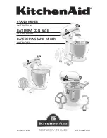
KSM170
Brand: KitchenAid Pages: 20

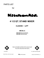
KSM500ER0
Brand: KitchenAid Pages: 10

KSM8990ER
Brand: KitchenAid Pages: 48
KPM5 WH
Brand: KitchenAid Pages: 2
KSM450BK0
Brand: KitchenAid Pages: 10

KJG01A Series
Brand: KitchenAid Pages: 16

KHM9PWH - 9 Speed Professional Hand Mixer
Brand: KitchenAid Pages: 28

KSM7990
Brand: KitchenAid Pages: 48
W10399721A
Brand: KitchenAid Pages: 12

KSM3311
Brand: KitchenAid Pages: 6

Professional 600 Series
Brand: KitchenAid Pages: 15

TILT-HEAD STAND MIXER
Brand: KitchenAid Pages: 21


