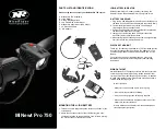
background image

cap lamp systems

luminator

®

power cell

817177 13 AH

luminator

®

power cell plus

817178 16 AH

instructions

PITTSBURGH, PENNSYLVANIA, U.S.A. 15230

Manufactured by

THIS MANUAL, INCLUDING THE WARNINGS AND CAUTIONS INSIDE,
MUST BE READ AND FOLLOWED CAREFULLY BY ALL PERSONS WHO
USE OR MAINTAIN THIS PRODUCT, INCLUDING THOSE WHO HAVE ANY
RESPONSIBILITY INVOLVING ITS SELECTION, APPLICATION, SERVICE,
OR REPAIR. THIS RESPIRATOR WILL PERFORM AS DESIGNED ONLY IF
USED AND MAINTAINED ACCORDING TO THE INSTRUCTIONS. OTHER-
WISE IT COULD FAIL TO PERFORM AS DESIGNED AND PERSONS WHO
RELY ON THIS PRODUCT COULD SUSTAIN SERIOUS PERSONAL INJURY
OR DEATH.

WARNING

The warranties made by MSA with respect to the product are voided if the
product is not installed, used, and serviced in accordance with the instruc-
tions in this manual. We encourage our customers to write or call for a
demonstration of this equipment prior to use or for any additional informa-
tion relative to use or repairs. Call 1-800-MSA-2222.

TAL 998 (L) Rev. 2

© MSA 1999

Print Spec. 10000005389 (S)   Mat. 817184

Doc. 817184

and ML-2

Ultralight

13 AH - 817171

Ultralight

16 AH - 817172

Ultralight w/Remote

13 AH - 817169

Ultralight w/Remote

16 AH - 817170

ML-2

13 AH - 817173

ML-2

16 AH - 817174

ML-2 w/Remote

16 AH - 817176

Ultralight

TM

817184  8/13/99  9:42 AM  Page 1

Summary of Contents for 817169

Page 1: ... AND PERSONS WHO RELY ON THIS PRODUCT COULD SUSTAIN SERIOUS PERSONAL INJURY OR DEATH WARNING The warranties made by MSA with respect to the product are voided if the product is not installed used and serviced in accordance with the instruc tions in this manual We encourage our customers to write or call for a demonstration of this equipment prior to use or for any additional informa tion relative ...

Page 2: ... and bat tery after each use and maintain them according to MSA s instructions Repairs must be made by properly trained per sonnel only 6 Follow MSA s instructions for first time and routine cap lamp use The battery must not be left on charge indefinitely see Storing Idle Batteries section Doing so may cause internal gases to vent which may lead to accumulation of combustible gases in the lamp roo...

Page 3: ...f each cell with distilled water if necessary see Watering section Routine Battery Maintenance 1 Routine Charging on Standard Rack and Charger All batteries in this category must be charged immediately after each period of use in the following manner a Set power supply or charging stations to 5 0 05 VDC b Connect the battery to the charging station following the instructions supplied with the char...

Page 4: ...ttery is charged Water only when battery is fully charged If the battery is over topped there is a possibility that electrolyte may leak out under cer tain conditions a Fill the plastic bottle of the MSA Filling Device P N 69422 469773 or 454052 with dis tilled water only and place it at a convenient location close to the batteries to be watered b Insert the nozzle or needle of the Filling Tube in...

Page 5: ...e reflector tight against the cover bezel An O ring mounted in a groove in the lamp housing seals against the bezel to help keep out dirt and moisture A stainless steel clip holds the head piece firmly to the miner s cap A durable abrasion resistant cable con nects the headpiece to the battery and allows freedom of movement Using the Ultralight Cap Lamp System The on off switch is a 3 position swi...

Page 6: ... 632227 out of the lamp housing Removing the Secondary Bulb P N 476720 1 Gently pull the bulb until the pins are free of the circuit board Installing a new O Ring 1 Place a small amount of silicone lubricant on the O ring 2 Gently stretch the O ring over the lamp housing and place it in the groove Installing a new Main Bulb and Reflector Assembly 1 Insert the bulb and reflector into the spring 2 C...

Page 7: ...ring and the secondary bulb 3 Remove the main circuit board 4 Using a wrench loosen and remove the boot P N 682390 Keep the boot it will be used to secure the new switch Take care not to damage the boot material 5 Pull the switch and wiring out of the lamp housing Installing the Switch and Wiring Assembly 1 Position the switch so that the blue wire is closest to the open end of the lamp housing an...

Page 8: ...washer P N 56874 and the con tact wire assembly P N 484821 the white wire Re installing the Charging Barrel Charging Contact and Contact Wire Assembly 1 Insert the screw into the charging contact then insert the screw into the hole in the center of the lamp housing 2 Temporarily insert the charging barrel to hold the charging contact and screw in place 3 Install the contact wire assembly white wir...

Page 9: ...le with soapy water and insert it into the cover by pushing each terminated conductor one at a time through the cable protector Continue pushing cable until 3 1 4 of cable sheath is exposed inside the cover Wrap cable around and through circular bosses molded in the cover and press firmly to inside top of cover Secure in place by assembling cable retaining wash ers and screws 4 Clean any foreign m...

Page 10: ...10 TAL 998 L Rev 2 817184 Notes Ultralight Cap Lamp System Expanded Parts Diagram 817184 8 13 99 9 43 AM Page 10 ...

Page 11: ...817184 8 13 99 9 43 AM Page 11 ...

Page 12: ...817184 8 13 99 9 43 AM Page 12 ...

Page 13: ...adjust the light beam to a spot or wide beam 3 After use turn the switch knob until the bulb is off Note In the case of the primary filament burning out the safety filament may be switched on by continuing to turn the switch knob Check the bulb to be sure both filaments are in working order before use ML 2 MAINTENANCE Replacing Bulb 1 Insert 3 32 hexagon wrench into the socket located at the botto...

Page 14: ...ssembly Replacing Cable 1 To separate the headpiece cable and cover remove battery cover clamp screws one on each side Slide cover clamps off sideways Lift cover to permit access to cable clamp screws loosen them and carefully pry cable clamps off the battery poles 2 To separate the cable from the cover remove cable retaining screws and washers then lift the cable away from the circular boss es mo...

Page 15: ...ach terminated conductor one at a time through the cable protector Continue pushing cable until 3 1 4 of cable sheath is exposed inside the cover Wrap cable around and through circular bosses molded in the cover and press firmly to inside top of cover Secure in place by assembling cable retaining wash ers and screws 8 Clean any foreign matter form each battery pole 9 Fasten red conductor to positi...

Page 16: ...14 TAL 998 L Rev 2 817184 ML 2 Cap Lamp System Expanded Parts Diagram Notes 817184 8 13 99 9 44 AM Page 16 ...

Page 17: ...817184 8 13 99 9 44 AM Page 17 ...

Page 18: ...817184 8 13 99 9 44 AM Page 18 ...

Page 19: ...adpiece in the same manner as those on the battery e Make sure the bulb is secure and making good contact f If the light flickers or dims when any of the preceding items are being checked that item should be repaired or replaced g If battery appears warm on charge this is normal and is not necessarily an indication that anything is wrong with the battery 3 Electrolyte Level a Check at least once e...

Page 20: ...PITTSBURGH PENNSYLVANIA U S A 15230 Manufactured by 817184 8 13 99 9 44 AM Page 20 ...

Reviews: