

— 1 —
— 2 —
— 3 —
NPort 5600 Series
Quick Installation Guide
Fourth Edition, August 2004
1. Overview
Welcome to the MOXA NPort 5600 Series of advanced serial device servers,
which make it easy for you to network-enable your serial devices. NPort
5610-16/8 comes with 16/8 RS-232 ports, and NPort 5630-16/8 comes with
16/8 RS-422/485 ports.
2. Package Checklist
Before installing NPort 5600, verify that the package contains the following
items:
y
1 16-port or 8-port serial device server
y
NPort Documentation & Software CD
y
NPort 5600 Quick Installation Guide
y
Power cord (included with AC version of the product)
Optional Accessories
y
CBL-RJ45M9-150
y
CBL-RJ45F9-150
y
CBL-RJ45M25-150
y
CBL-RJ45F25-150
8-pin RJ45 to Male DB9 cable, 150 cm
8-pin RJ45 to Female DB9 cable, 150 cm
8-pin RJ45 to Male DB25 cable, 150 cm
8-pin RJ45 to Female DB25 cable, 150 cm
Notify your sales representative if any of the above items is missing or
damaged.
3. Hardware Introduction
The NPort 5600 Series has 6 models: NPort 5610-16, NPort 5610-8, NPort
5610-16-48V, NPort 5610-8-48V, NPort 5630-16, and NPort 5630-8. The
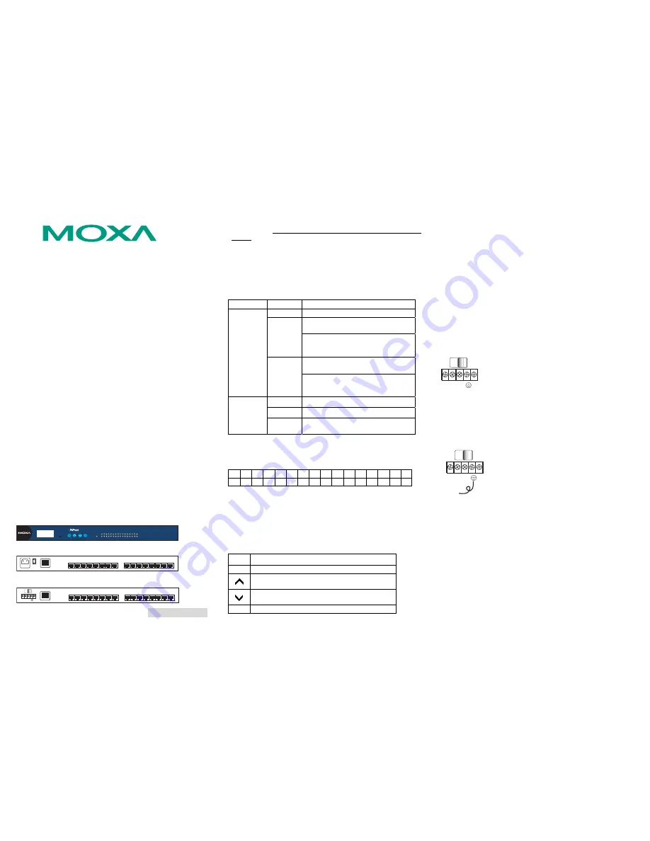
following figures show the front and rear panel of NPort 5600.
Front panel of NPort 5600 Series
1
2
3
4
5
6
7
8
9
10
11
12
13
14
15
16
Tx
Rx
Ready
MENU
SEL
5610-16-48V
Reset
Rear panel of NPort 5610-16 (AC Power)
2
3
4
5
6
7
8
9
1
2
3
4
5
6
7
8
Serial ports
O
I
13 14 15 16
9
10 11 12
LAN
AC POWER 100-240V, 47-63 Hz
Rear panel of NPort 5610-16-48V (DC Power)
2
3
4
5
6
7
8
9
1
2
3
4
5
6
7
8
Serial ports
13 14 15 16
9
10 11 12
LAN
V+ V-
ON
OFF
Reset Button
—Press the
Reset button
continuously for
5 sec to load factory
defaults
: Use a pointed object, such as a straightened paper clip or toothpick,
to press the reset button. This will cause the Ready LED to blink on and off.
The factory defaults will be loaded once the Ready LED stops blinking (after
about 5 seconds). At this point, you should release the reset button.
LED Indicators
The front panels of NPort 5600 have several LED indicators, as described in
the following table.
LED Name
LED Color
LED Function
off
Power is off, or power error condition exists.
Steady on: Power is on and NPort is
booting up.
red
Blinking:
Indicates an IP conflict, or
DHCP or BOOTP server did
not respond properly.
Steady on: Power is on and NPort is
functioning normally.
Ready
green
Blinking:
The NPort has been located by
NPort Administrator’s
Location function.
orange
Serial port is receiving data.
green
Serial port is transmitting data.
1-16
off
No data is being transmitted or received
through the serial port.
LCM Display Panel
—If the NPort is working properly, the LCM panel will
display a green color. The red Ready LED will also light up, indicating that
the NPort is receiving power. After the red Ready LED turns green, you will
see a display similar to:
N
P
5
6
1
0
-
1
6
_
3
8
1
9
2
.
1
6
8
.
1
2
7
.
2
5
4
This is where
z
NP5610-16
is
the
NPort’s
name
z
38
is
the NPort’s serial number
z
192.168.127.254
is the NPort’s IP address
LCM Panel Operation
—There are four buttons on NPort 5600’s front panel.
These buttons are used to operate the server’s LCM panel. Going from left to
right, the buttons are:
Button Action
MENU
Activates the main menu, or returns to an upper level.
Scrolls up through a list of items shown on the LCM
panel’s second line.
Scrolls down through a list of items shown on the LCM
panel’s second line.
SEL
Selects the option listed on the LCM panel’s second line.
Detailed LCM Panel Operating instructions can be found on the CD-ROM in
the “NPort 5600 Series User’s Manual.”
4. Hardware Installation Procedure
STEP 1
: After removing NPort 5600 from the box, the first thing you should
do is attach the power adaptor.
STEP 2
: Connecting the Power
AC: Connect the NPort 5610/5630 100-240 VAC power cord to the AC
connector. If the power connection is correct, the “Ready” LED will
show a solid red color until the system is ready, at which time the
“Ready” LED will change to a green color.
DC: Connect NPort 5610-16/8-48V’s power cord to the DC connector, and
then follow the steps given below:
V+ V-
ON
OFF
1.
Loosen the screws on the V
+
and V
-
terminals of
NPort 5610-8/16-48V’s terminal block.
2.
Connect the power cord’s 48 VDC or -48 VDC wire
to the terminal block’s V
+
terminal, and the power
cord’s DC Power Ground wire to the terminal block’s
V
-
terminal, and then tighten the terminal block
screws. (Note: NPort 5610-8/16-48V can still operate
even if the 48V/-48V and DC Power Ground are
reversed.)
If the power is connected properly, the “Ready” LED will show a solid red
color until the system is ready, at which time the “Ready” LED will change to
a green color.
Grounding NPort 5610-16/8-48V:
V+ V-
SG
ON
OFF
Grounding and wire routing helps limit the effects of
noise due to electromagnetic interference (EMI). Run
the ground connection from the
ground screw to the
grounding surface prior to connecting devices. The
Shielded Ground (sometimes called Protected
Ground) contact is the second contact from the right
of the 5-pin power terminal block connector located
on the rear panel of NPort 5610-8/16-48V. Connect
the SG wire to the Earth ground.
STEP 3
: Connect NPort 5600 to a network. Use a standard straight-through
Ethernet cable to connect to a Hub or Switch. When setting up or testing
NPort 5600, you might find it convenient to connect directly to your
computer’s Ethernet port. In this case, use a cross-over Ethernet cable.
STEP 4
: Connect NPort 5600’s serial port to a serial device.
Placement Options
: You can place NPort 5600 on a desktop or other
horizontal surface.
P/N: 18020561002


