background image

control

 – motion – interface

motrona GmbH 
Zwischen den Wegen 32 
78239 Rielasingen - Germany 
Tel. +49 (0)7731-9332-0 
Fax +49 (0)7731-9332-30 
[email protected]
www.motrona.com 

IX34208a_e.doc / Aug-09 


Page 1 / 40 

IX 342 

SSI Indicator with Two Relay Outputs

and Serial Interface, for Use with

Single-Turn or Multi-Turn SSI Encoders 

x

Clear LED display (15 mm / 0.59’’ size) with adjustable brightness

x

Master- or Slave operation with clock rates up to 1 MHz 

x

Suitable for all SSI formats up to 25 bits 

x

Two presets and relay outputs 

x

Serial RS232 / RS485 interface 

x

Numerous supplementary functions like Linearization, Bit Blanking etc. 

Operating Instructions 

Summary of Contents for IX 342

Page 1: ...ith Two Relay Outputs and Serial Interface for Use with Single Turn or Multi Turn SSI Encoders x Clear LED display 15 mm 0 59 size with adjustable brightness x Master or Slave operation with clock rat...

Page 2: ...s a must to observe all general and also all country specific and application specific safety standards x When this unit is used with applications where failure or maloperation could cause damage to a...

Page 3: ...s 10 3 2 Overview of Operational Parameters 11 4 Setup Procedure 12 4 1 Basic Parameters 12 4 2 Operational Parameters 14 4 3 Parameters for Preselections and Relay Outputs 17 4 4 Parameters for Setup...

Page 4: ...CD IN 1 2 3 4 5 6 7 8 9 10 INPUT A INPUT B RESET C 24VDC OUT TXD B RXD A GND GND 1 2 3 1 2 3 X1 X2 X3 C NO NC C NO NC Rel 1 Rel 2 X4 1 2 3 4 CLK CLK DAT DAT Rel 2 Rel 1 TxD RxD GND SSI Absolute Encode...

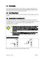
Page 5: ...d to PNP signal must switch to or to NPN signal must switch to This configuration is valid for all three inputs at a time The factory setting is always PNP x Independent of your setting all functions...

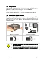
Page 6: ...mmunication This setting can be changed to RS485 2 wire by means of an internal DIL switch To access the DIL switch you must remove the screw terminal connectors and the backplane Then pull the board...

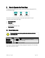
Page 7: ...display state x Setup state a Basic setup b Operational parameter setup x Teach operation 2 1 Normal display state You can only change over to other operation states while the unit is in the normal d...

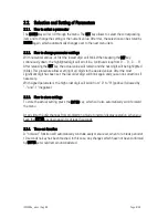
Page 8: ...git will be highlighted blink This procedure allows setting of all digits to the desired values After the most significant digit has been set the low order digit will blink again and you can do correc...

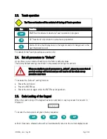
Page 9: ...he factory default values The factory default settings are shown in the parameter listings in section 6 When you decide to set all parameters to default please be aware that all previous settings will...

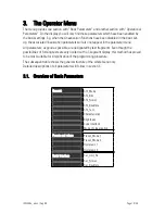
Page 10: ...sible are designated by text fragments Even though the possibilities of forming texts are very limited with a 7 segment display this method has proved to be most suitable for simplification of the pro...

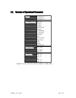
Page 11: ...2 Display and Scaling M Factor D Factor P Factor Decimal point Display Hi_Bit MSB Lo_Bit LSB Direction Error Error_Polarity Round loop Time Reset Zero Position Serial Interface Ser_Timer Ser_Mode Ser_...

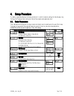
Page 12: ...NPN and the desired brightness of the LED display Menu Setting Range Default SSI Mode Setting of Master Mode or Slave Mode For details see section 5 1 SSI Bits Bit length of the SSI string For details...

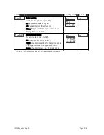
Page 13: ...ions P Free Keypad interlock except for Preselection Settings Pres 1 und Pres 2 Linearization Mode For details please see 6 1 und 6 2 no Linearization is switched OFF 1 qua Linearization settings for...

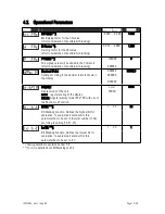
Page 14: ...ng to the decimal formats shown in the display 000000 00000 0 0 00000 00000 0 Display Display mode of the unit norm regular scaling of the display 359 59 Angular display format 359 59 with use of the...

Page 15: ...occurs Err b appears on the display The same function can also be used to monitor the Power Failure Bit of an encoder mostly called PFB Round Loop Defines the number of encoder steps per revolution wi...

Page 16: ...When you set this parameter to e g 1024 the unit will display zero when the encoder position is 1024 Zero Position can be set directly via keypad or by means of an external Reset command 199999 99999...

Page 17: ...hen Display Value Preselection1 timed output pulse Switching Characteristics of Relay 2 See above but Preselection2 See above but Preselection2 See above but Preselection2 See above but Preselection2...

Page 18: ...switch points will result Preselection Hysteresis GE Greater Equal Display Value Hysteresis effect with Greater Equal Preselection LE Lower Equal Hysteresis Display Value Hysteresis effect with Lower...

Page 19: ...y unit number between 11 and 99 The address must however not contain a 0 because such numbers are reserved for collective addressing of several units 0 99 1 11 Serial Data Format The first character i...

Page 20: ...aud rate The minimum cycle times for timer transmissions are shown in the table Baud Rate Minimum Cycle Time ms 600 384 1200 192 2400 96 4800 48 9600 24 19200 12 38400 6 Serial Mode PC Operation accor...

Page 21: ...Request string for readout of the actual display data from a unit with serial address No 11 ASCII Code EOT 1 1 1 ENQ Hex 04 31 31 3A 31 05 Binary 0000 0100 0011 0001 0011 0001 0011 1010 0011 0001 000...

Page 22: ...Carriage return X X X X X X LF CR Print2 Sign Data Carriage return X X X X X X CR The mode of activation of serial transmissions can be determined as follows Cyclic timed transmissions Set the Serial...

Page 23: ...this case both clock terminals CLK are configured as inputs 6 GND SSI Indicator with Slave Operation Clock Clock Data Data SSI Encoder Remote Master Clock Clock Data Data CLK DAT CLK DAT SSI Indicator...

Page 24: ...must be blanked by corresponding setting of parameters Hi_bit and Lo_bit For successful use of the bit blanking function it is important to observe the relevant hints given under chapter 5 2 5 2 Eval...

Page 25: ...limited to a maximum range of 6 decades SSI encoders with a resolution of more than 19 bits will however generate SSI data with more than 6 decades In such a case it can become difficult to set the 0...

Page 26: ...ensure that the unit displays the pure SSI encoder information at first x Move your encoder now from a lower position towards a higher position according to your own definition of low and high When a...

Page 27: ...lay 45o o 0o 7168 360o Encoder 13Bit Direction 0 0 Position 1024 Course of display with positive counting direction 8192 0 PoS 1024 360 180 degrees 1024 Original encoder signal Display 45o o 0o o 7168...

Page 28: ...f steps for one loop For setup please proceed first like shown under section 5 4 1 Then set register r LooP to the number of steps corresponding to one revolution of the table You are free to scale th...

Page 29: ...on from maximum to zero This feature can help to avoid mechanical adjusting of the encoder zero position with many applications when no other means for the mechanical zero definition is available In g...

Page 30: ...mode only the data lines are subject of this test Cd Clock and data function test The next test generates clock and data signals and feeds them directly into the rear terminals Therefore please remove...

Page 31: ...would normally show in the display With parameters P01_y to P16_y you can specify which values you would like to display instead of the corresponding _x values This means e g that the unit will replac...

Page 32: ...ning is picked up by means of an SSI encoder We would like to display the clearance of the gate d but the existing encoder information is proportional to the opening angle d 1 cos SSI Encoder d d0 Dis...

Page 33: ...tEACh Now the unit has switched over to the Teach mode To start the teach procedure please press again Cmd within the next 10 seconds The display will then show P01_X x With respect to the consistency...

Page 34: ...nstraint valid for the x values of interpolation points Every interpolation point must be higher than its preceding point Where this constraint is breached all 6 decimal points will blink automaticall...

Page 35: ...8a_e doc Aug 09 Page 35 40 7 Technical Appendix 7 1 Dimensions 96 0 3 780 110 0 4 331 44 0 1 732 10 0 394 8 0 315 91 0 3 583 9 0 345 129 0 5 079 140 5 5 531 48 0 1 890 Panel cut out 91 x 44 mm 3 583 x...

Page 36: ...ncy range 100 Hz 1 MHz Min pulse duration for Reset 5 msec Serial interface RS 232 or RS 485 switch selectable 600 38400 bauds Ambient temperature Operation 0 45 C 32 113 F Storage 25 70 C 13 158 F Ho...

Page 37: ...4 3 09 P Factor PFAc 199999 999999 0 6 0 10 Decimal Point dPoint 0 5 0 1 0 11 Display diSPLA 0 1 0 1 0 12 Hi_Bit MSB Hi_bit 1 25 1 2 0 13 Lo_Bit LSB Lo_bit 1 25 25 2 0 14 Direction dir 0 1 0 1 0 15 Er...

Page 38: ...99999 999999 6 0 A9 Linear Point 6 P06_H 199999 999999 999999 6 0 B0 P06_Y 199999 999999 999999 6 0 B1 Linear Point 7 P07_H 199999 999999 999999 6 0 B2 P07_Y 199999 999999 999999 6 0 B3 Linear Point 8...

Page 39: ...Mode 1 Presel Mode 2 Hysteresis 1 Hysteresis 2 Serial Interface Serial Unit Nr Serial Format Serial Baud Rate Display Parameters M Factor Decimal Point D Factor Display P Factor SSI Special SSI High...

Page 40: ...doc Aug 09 Page 40 40 Linearization P1 x P1 y P9 x P9 y P2 x P2 y P10 x P10 y P3 x P3 y P11 x P11 y P4 x P4 y P12 x P12 y P5 x P5 y P13 x P13 y P6 x P6 y P14 x P14 y P7 x P7 y P15 x P15 y P8 x P8 y P...

Reviews: