Motorola PDR 3500, Basic Service Manual
The Motorola PDR 3500 user manual is an essential tool for efficient performance and maintenance. It provides detailed Tune-Up Instructions for optimum device functionality. Download this comprehensive manual for free from our website and ensure seamless operations of your Motorola PDR 3500.
Share
Download


Reviews:
No comments
Related manuals for PDR 3500

6410
Brand: Lasko Pages: 4

OCEACV100IFW2
Brand: Oceanic Pages: 201

PATRON E9
Brand: Patron Pages: 8

07182
Brand: EDM Product Pages: 25

MX920
Brand: Spectra Pages: 2

SHOPHEATER
Brand: Mark Pages: 80

Heaters
Brand: Ariston Pages: 11

KLIMATRONIC 11597
Brand: Suntec Wellness Pages: 86

SK series
Brand: Minib Pages: 2

38-6814
Brand: Exibel Pages: 5

DCH5915ER
Brand: DeLonghi Pages: 14

SRE 260
Brand: Zibro Pages: 85

2531DL-0078
Brand: DeWalt Pages: 108

KX-TGA405EX
Brand: Panasonic Pages: 4
KX-A406
Brand: Panasonic Pages: 2

VL-FKD2BX
Brand: Panasonic Pages: 12
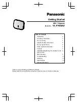
VL-FKD2AZ
Brand: Panasonic Pages: 12

VL-FAN1BX
Brand: Panasonic Pages: 20


