Motorola EX-3524, Installation Manual
The Motorola EX-3524 is a high-performance Ethernet switch designed to meet your networking needs. This versatile device offers seamless connectivity and advanced features. To get started, simply visit manualshive.com to download the free installation manual, providing comprehensive instructions for easy setup and operation.
Share
Download


Reviews:
No comments
Related manuals for EX-3524

NI 9265
Brand: National Instruments Pages: 26

NI 9203
Brand: National Instruments Pages: 85

Module SCXI-1503
Brand: National Instruments Pages: 79

DSR-500
Brand: D-Link Pages: 213

MasterBus Tanklevel Interface
Brand: Mastervolt Pages: 8

JDR454WV4
Brand: Justec Pages: 61

TD-3316B4-16P-A1
Brand: TVT Digital Pages: 2

NetVanta 873
Brand: ADTRAN Pages: 2

ION 1000
Brand: PaloAlto Networks Pages: 28
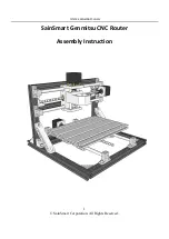
Genmitsu CNC
Brand: SainSmart Pages: 12

iConverter GX/F
Brand: Omnitron Systems Technology Pages: 2

WST-375L
Brand: U-Media Pages: 42
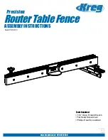
PRS1010
Brand: Kreg Pages: 24
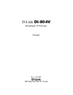
DI-804V
Brand: D-Link Pages: 52

DES-1252 - Web Smart Switch
Brand: D-Link Pages: 11

DES-1228 - Web Smart Switch
Brand: D-Link Pages: 4

DHP-347AV
Brand: D-Link Pages: 32

DHP-347AV
Brand: D-Link Pages: 26


