background image

DSP56305

24-Bit Digital Signal Processor

User’s Manual

Motorola, Incorporated
Semiconductor Products Sector
DSP Division
6501 William Cannon Drive West
Austin, TX  78735-8598

Summary of Contents for DSP56305

Page 1: ...DSP56305 24 Bit Digital Signal Processor User s Manual Motorola Incorporated Semiconductor Products Sector DSP Division 6501 William Cannon Drive West Austin TX 78735 8598 ...

Page 2: ... Motorola does not assume any liability arising out of the application or use of any product or circuit described herein neither does it convey any license under its patent rights nor the rights of others Motorola products are not authorized for use as components in life support devices or systems intended for surgical implant into the body or intended to support or sustain life Buyer agrees to no...

Page 3: ... 1 2 Multiplier Accumulator MAC 1 9 1 6 2 Address Generation Unit AGU 1 9 1 6 3 Program Control Unit PCU 1 10 1 6 4 PLL and Clock Oscillator 1 11 1 6 5 JTAG TAP and On Chip Emulation OnCE Module 1 11 1 6 6 On Chip Memory 1 12 1 6 7 Off Chip Memory Expansion 1 13 1 7 INTERNAL BUSES 1 13 1 8 DSP56305 BLOCK DIAGRAM 1 14 1 9 DIRECT MEMORY ACCESS DMA 1 15 1 10 DSP56305 ARCHITECTURE OVERVIEW 1 15 1 10 1...

Page 4: ...RFACE 0 ESSI0 2 28 2 10 ENHANCED SYNCHRONOUS SERIAL INTERFACE 1 ESSI1 2 32 2 11 SERIAL COMMUNICATION INTERFACE SCI 2 35 2 12 TIMERS 2 36 2 13 JTAG ONCE INTERFACE 2 38 SECTION 3 MEMORY CONFIGURATION 3 1 3 1 MEMORY SPACES 3 3 3 1 1 Program Memory Space 3 3 3 1 1 1 Program RAM 3 4 3 1 1 2 Bootstrap ROM 3 4 3 1 2 Data Memory Spaces 3 5 3 1 2 1 X Data Memory Space 3 5 3 1 2 2 Y Data Memory Space 3 6 3 ...

Page 5: ...hrough HI32 in 16 Bit Wide UB Mode ISA 4 10 4 3 10 Mode E Bootstrap Through HI32 in 8 Bit Wide UB Mode in Double Strobe Pin Configuration 4 10 4 3 11 Mode F Bootstrap Through HI32 in 8 Bit Wide UB Mode in Single Strobe Pin Configuration 4 11 4 4 RTOS PROGRAM 4 11 4 5 INTERRUPT SOURCES AND PRIORITIES 4 11 4 5 1 Interrupt Sources 4 12 4 5 2 Interrupt Priority Levels 4 15 4 5 3 Interrupt Source Prior...

Page 6: ...in Universal Bus Modes 6 8 6 3 HI32 RESETS 6 9 6 4 HI32 BLOCK DIAGRAM 6 10 6 5 DSP SIDE PROGRAMMING MODEL 6 11 6 5 1 DSP Control Register DCTR 6 12 6 5 1 1 Host Command Interrupt Enable HCIE Bit 0 6 13 6 5 1 2 Slave Transmit Interrupt Enable STIE Bit 1 6 13 6 5 1 3 Slave Receive Interrupt Enable SRIE Bit 2 6 13 6 5 1 4 Host Flags HF 5 3 Bits 5 3 6 13 6 5 1 5 Host Interrupt A HINT Bit 6 6 13 6 5 1 ...

Page 7: ...mplete Interrupt Enable TCIE Bit 12 6 23 6 5 2 8 Clear Transmitter CLRT Bit 14 6 23 6 5 2 9 Master Transaction Termination MTT Bit 15 6 24 6 5 2 10 System Error Force SERF Bit 16 6 24 6 5 2 11 Master Access Counter Enable MACE Bit 18 6 25 6 5 2 12 Master Wait State Disable MWSD Bit 19 6 25 6 5 2 13 Receive Buffer Lock Enable RBLE Bit 20 6 26 6 5 2 14 Insert Address Enable IAE Bit 21 6 27 6 5 2 15 ...

Page 8: ...ta Request MRRQ Bit 2 6 40 6 5 6 4 Master Address Request MARQ Bit 4 6 40 6 5 6 5 Address Parity Error APER Bit 5 6 40 6 5 6 6 Data Parity Error DPER Bit 6 6 41 6 5 6 7 Master Abort MAB Bit 7 6 41 6 5 6 8 Target Abort TAB Bit 8 6 41 6 5 6 9 Target Disconnect TDIS Bit 9 6 41 6 5 6 10 Target Retry TRTY Bit 10 6 42 6 5 6 11 PCI Time Out TO Bit 11 6 42 6 5 6 12 Host Data Transfer Complete HDTC Bit 12 ...

Page 9: ...st Receive Data Request HRRQ Bit 2 6 70 6 6 2 4 Host Flags HF5 HF3 Bits 5 4 and 3 6 70 6 6 2 5 Host Interrupt A HINT Bit 6 6 70 6 6 2 6 Host Request HREQ Bit 7 6 71 6 6 2 7 HSTR Reserved Status Bits 31 8 6 71 6 6 3 Host Command Vector Register HCVR 6 72 6 6 3 1 Host Command HC Bit 0 6 73 6 6 3 2 Host Vector HV6 HV0 Bits 7 1 6 74 6 6 3 3 Host Non Maskable Interrupt HNMI Bit 15 6 74 6 6 3 4 HCVR Res...

Page 10: ...tion Register CHTY CLAT 6 84 6 6 10 1 Header Type HT7 HT0 Bits 23 16 6 84 6 6 10 2 Latency Timer LT7 LT0 Bits 15 8 6 85 6 6 10 3 CHTY CLAT Not Implemented Bits 31 24 7 0 6 85 6 6 11 Memory Space Base Address Configuration Register CBMA 6 86 6 6 11 1 Memory Space Indicator MSI Bit 0 6 86 6 6 11 2 Memory Space MS1 MS0 Bits 2 and 1 6 87 6 6 11 3 Pre fetch PF Bit 3 6 87 6 6 11 4 Memory Base Address PM...

Page 11: ...A Bit 11 7 15 7 4 1 4 Frame Rate Divider Control DC 4 0 CRA Bits 16 12 7 16 7 4 1 4 1 Normal Mode MOD 0 7 17 7 4 1 4 2 Network Mode MOD 1 DC 00000 7 17 7 4 1 4 3 On Demand Mode MOD 1 DC 00000 7 17 7 4 1 5 Reserved CRA Bit 17 7 18 7 4 1 6 Alignment Control ALC CRA Bit 18 7 18 7 4 1 7 Word Length Control WL 2 0 CRA Bits 21 19 7 19 7 4 1 8 Select SC1 as Transmitter 0 Drive Enable SSC1 CRA Bit 22 7 19...

Page 12: ... RIE CRB Bit 19 7 34 7 4 2 20 ESSI Transmit Last Slot Interrupt Enable TLIE CRB Bit 20 7 34 7 4 2 21 ESSI Receive Last Slot Interrupt Enable RLIE CRB Bit 21 7 34 7 4 2 22 ESSI Transmit Exception Interrupt Enable TEIE CRB Bit 22 7 35 7 4 2 23 ESSI Receive Exception Interrupt Enable REIE CRB Bit 23 7 35 7 4 3 ESSI Status Register SSISR 7 35 7 4 3 1 Serial Input Flag 0 IF0 SSISR Bit 0 7 35 7 4 3 2 Se...

Page 13: ...rame Sync Signal Format 7 51 7 5 3 5 2 Frame Sync Length for Multiple Devices 7 51 7 5 3 5 3 Word Length Frame Sync Position 7 51 7 5 3 5 4 Frame Sync Polarity 7 52 7 5 3 6 Selecting the Bit Shift Order for the Transmitter 7 52 7 5 4 ESSI Flag Usage 7 53 7 6 GPIO ESSI SELECTION AND GPIO USAGE 7 53 7 6 1 Port Control Register PCR 7 54 7 6 2 Port Direction Register PRR 7 55 7 6 3 Port Data Register ...

Page 14: ...E SSR Bit 0 8 14 8 3 2 2 Transmit Data Register Empty TDRE SSR Bit 1 8 14 8 3 2 3 Receive Data Register Full RDRF SSR Bit 2 8 15 8 3 2 4 Idle Line Flag IDLE SSR Bit 3 8 15 8 3 2 5 Overrun Error Flag OR SSR Bit 4 8 15 8 3 2 6 Parity Error PE SSR Bit 5 8 16 8 3 2 7 Framing Error Flag FE SSR Bit 6 8 16 8 3 2 8 Received Bit 8 Address R8 SSR Bit 7 8 16 8 3 3 SCI Clock Control Register SCCR 8 17 8 3 3 1...

Page 15: ... Reserved Bit TPLR Bit 23 9 6 9 2 5 Timer Prescaler Count Register TPCR 9 7 9 2 5 1 Prescaler Counter Value PC 20 0 TPCR Bits 20 0 9 7 9 2 5 2 Reserved Bits TPCR Bits 23 21 9 7 9 3 TIMER ARCHITECTURE 9 7 9 3 1 Timer Block Diagram 9 9 9 3 2 Timer Programming Model 9 9 9 3 3 Timer Control Status Register TCSR 9 10 9 3 3 1 Timer Enable TE TCSR Bit 0 9 11 9 3 3 2 Timer Overflow Interrupt Enable TOIE T...

Page 16: ... Width Mode 4 9 23 9 4 2 3 Measurement Input Period Mode 5 9 24 9 4 2 4 Measurement Capture Mode 6 9 25 9 4 3 Pulse Width Modulation PWM Mode 7 9 26 9 4 4 Watchdog Modes 9 27 9 4 4 1 Watchdog Pulse Mode 9 9 27 9 4 4 2 Watchdog Toggle Mode 10 9 28 9 4 5 Reserved Modes 9 29 9 4 6 Special Cases 9 29 9 4 6 1 Timer Behavior during Wait 9 29 9 4 6 2 Timer Behavior during Stop 9 29 9 4 7 DMA Trigger 9 29...

Page 17: ... Limit Register 1 OMLR1 10 11 10 5 5 OnCE Memory Address Comparator 1 OMAC1 10 11 10 5 6 OnCE Breakpoint Control Register OBCR 10 12 10 5 6 1 Memory Breakpoint Select MBS0 MBS1 Bits 0 1 10 12 10 5 6 2 Breakpoint 0 Read Write Select RW00 RW01 Bits 2 3 10 12 10 5 6 3 Breakpoint 0 Condition Code Select CC00 CC01 Bits 4 5 10 13 10 5 6 4 Breakpoint 1 Read Write Select RW10 RW11 Bits 6 7 10 13 10 5 6 5 ...

Page 18: ...AL PROTOCOL 10 23 10 11 TARGET SITE DEBUG SYSTEM REQUIREMENTS 10 23 10 12 EXAMPLES OF USING THE ONCE 10 24 10 12 1 Whether the Chip has Entered the Debug Mode 10 24 10 12 2 Polling the JTAG Instruction Shift Register 10 24 10 12 3 Saving Pipeline Information 10 25 10 12 4 Reading the Trace Buffer 10 25 10 12 5 Displaying a Specified Register 10 26 10 12 6 Displaying X Memory Area Starting at Addre...

Page 19: ...12 4 12 3 BLOCK DESCRIPTION 12 4 12 3 1 Peripheral Module Bus PMB Interface 12 5 12 3 2 FCOP Memory Banks 12 6 12 3 3 Multiplier and Accumulator FMAC 12 6 12 4 PROGRAMMING MODEL 12 6 12 4 1 FCOP Registers 12 7 12 4 2 FCOP Data Input Register FDIR 12 8 12 4 3 FCOP Data Output Register FDOR 12 8 12 4 4 FCOP Coefficients Input Register FCIR 12 9 12 4 5 FCOP Filter Count Register FCNT 12 9 12 4 6 FCOP...

Page 20: ...g Real Outputs Only Decimation by 2 12 21 12 5 6 FCOP Mode 1 Full Complex FIR Filter 12 23 12 5 6 1 Mode 1 Full Complex FIR Filter No Decimation 12 23 12 5 6 2 Mode 1 Full Complex Correlation Filter No Decimation 12 25 12 5 6 3 Mode 1 Full Complex FIR Filter Decimation by 2 12 27 12 5 7 FCOP Mode 2 Full Complex FIR Filter 12 29 12 5 7 1 Mode 2 Complex FIR Filter Generating Pure Real or Pure Imagin...

Page 21: ...3 Flush Operation 13 11 13 4 2 Encoder Mode 13 12 13 4 2 1 Initialization 13 12 13 4 3 Decoder Mode 13 12 13 4 3 1 Initialization 13 13 13 4 3 2 Normal Operation 13 13 13 4 3 3 Flush Operation 13 14 13 4 4 Memory Access Mode 13 14 13 4 5 Flush Mode 13 14 13 4 6 VCOP Individual Reset State 13 15 13 4 7 Idle State 13 15 13 5 PROGRAMMING MODEL 13 16 13 5 1 Viterbi Data Register FIFO VDR 13 17 13 5 2 ...

Page 22: ...RB Bit 12 13 22 13 5 4 10 Operation Complete Interrupt Enable OCIE VCRB Bit 13 13 22 13 5 4 11 Reserved Bits VCRB Bits 2 5 9 14 15 13 22 13 5 4 12 Internal Reserved Bits VCRB Bits 4 7 13 23 13 5 5 Viterbi Status Register VSTR 13 23 13 5 5 1 Initialize Flag INIT VSTR Bit 0 13 23 13 5 5 2 Flush Flag FLSH VSTR Bit 1 13 23 13 5 5 3 Operation Complete OPC VSTR Bit 4 13 23 13 5 5 4 Processing Done DONE ...

Page 23: ...S Bits 15 8 13 29 13 5 12 Viterbi WED Data Register VWED 13 29 13 5 13 Viterbi Memory Access Register VMEM 13 29 13 6 CHIP DESCRIPTION 13 30 13 6 1 Memory description 13 30 13 6 2 Interrupt and DMA Sources 13 31 13 6 3 I O Register and Related Interrupts for Different Modes 13 31 13 6 4 Soft Decision Format 13 32 13 7 VITERBI BUTTERFLY IMPLEMENTATION 13 33 13 8 PERFORMANCE ANALYSIS 13 34 13 9 PROG...

Page 24: ... A CSFTA 14 12 14 4 3 3 Step Function Table B CSFTB 14 12 14 4 3 4 Input Enable bits INE 3 0 CSFTB Bits 19 16 14 13 14 4 3 5 Output Enable bits OUTE 3 0 CSFTB Bits 23 20 14 14 14 4 4 CCOP Control Status Register CCSR 14 14 14 4 4 1 Enable bit CEN CCSR Bit 0 14 15 14 4 4 2 Processing Enable bit PREN CCSR Bit 1 14 15 14 4 4 3 Operating Mode bits OPM 1 0 CCSR Bits 5 4 14 15 14 4 4 4 Left Right Connec...

Page 25: ...ing One CFSR 14 22 14 5 2 2 Parity Coding Mode Using Two Concatenated CFSRs 14 22 14 6 PROGRAMMING CONSIDERATIONS 14 23 14 6 1 Input Phase 14 23 14 6 2 Run Phase 14 23 14 6 3 Output Phase 14 24 14 6 4 Cipher Mode Processing 14 24 14 6 4 1 Cipher Mode Initialization 14 25 14 6 4 2 Cipher Mode Output 14 25 14 6 5 Parity Coding Processing 14 26 14 6 5 1 Parity Coding Mode Initialization 14 27 14 6 5 ...

Page 26: ...TRODUCTION D 3 D 1 1 Peripheral Addresses D 3 D 1 2 Interrupt Addresses D 3 D 1 3 Interrupt Priorities D 3 D 1 4 DMA Requests D 3 D 1 5 Programming Sheets D 3 D 1 6 HI32 Registers Quick Reference Tables D 3 D 2 INTERNAL I O MEMORY MAP D 4 D 3 INTERRUPT ADDRESSES AND SOURCES D 11 D 4 INTERRUPT PRIORITIES D 13 D 5 DMA REQUEST SOURCES D 15 D 6 PROGRAMMING REFERENCE SHEETS D 16 D 7 QUICK REFERENCE TAB...

Page 27: ...mpatibility Mode 3 16 Figure 3 6 Sixteen Bit Compatibility Mode Instruction Cache Enabled 3 17 Figure 3 7 Sixteen Bit Compatibility Mode Memory Switch Enabled 3 18 Figure 3 8 Sixteen Bit Compatibility Mode Memory Switch Enabled Instruction Cache Enabled 3 19 Figure 4 1 Interrupt Priority Register C IPR C X FFFFFF 4 16 Figure 4 2 Interrupt Priority Register P IPR P X FFFFFE 4 17 Figure 4 3 DSP56305...

Page 28: ...lock Diagram 7 5 Figure 7 2 SCKn Pin Configuration 7 6 Figure 7 3 SCn0 Pin Configuration 7 8 Figure 7 4 SCn1 Pin Configuration 7 11 Figure 7 5 SCn2 Pin Configuration 7 12 Figure 7 6 ESSI Control Register A CRA ESSI0 X FFFFB5 ESSI1 X FFFFA5 7 13 Figure 7 7 ESSI Control Register B CRB ESSI0 X FFFFB6 ESSI1 X FFFFA6 7 13 Figure 7 8 ESSI Status Register SSISR ESSI0 X FFFFB7 ESSI1 X FFFFA7 7 13 Figure 7...

Page 29: ...etwork Mode Operation 7 28 Figure 7 19 ESSI Data Path Programming Model SHFD 0 7 38 Figure 7 20 ESSI Data Path Programming Model SHFD 1 7 39 Figure 7 21 ESSI Main Modes 7 48 Figure 7 22 GPIO ESSI Port Organization 7 54 Figure 7 23 Port Control Register PCR 7 54 Figure 7 24 Port Direction Register PRR 7 55 Figure 7 25 Port Data Register PDR 7 56 Figure 8 1 SCI Control Register SCR 8 6 Figure 8 2 SC...

Page 30: ...5 Timer Block Diagram 9 9 Figure 9 6 Timer Programming Model 9 10 Figure 10 1 OnCE Module Block Diagram 10 3 Figure 10 2 OnCE Module Multiprocessor Configuration 10 4 Figure 10 3 OnCE Controller Block Diagram 10 5 Figure 10 4 OnCE Command Register 10 5 Figure 10 5 OnCE Status and Control Register OSCR 10 8 Figure 10 6 OnCE Memory Breakpoint Logic 0 10 10 Figure 10 7 OnCE Breakpoint Control Registe...

Page 31: ...tion 12 24 Figure 12 7 Input and Output Stream for Full Complex Correlation Filter without Decimation 12 26 Figure 12 8 Input and Output Stream for Full Complex Filter with Decimation 12 28 Figure 12 9 Input Output Stream for Complex FIR Filter Generating Pure Real Pure Imaginary Outputs Alternately without Decimation 12 30 Figure 12 10 Input Output Stream for Complex FIR Filter Generating Pure Re...

Page 32: ...r VSTR 13 23 Figure 13 12 Viterbi Tap A Register VTPA 13 25 Figure 13 13 Viterbi Tap Register B VTPB 13 26 Figure 13 14 Viterbi Trellis Setup Register VTSR 13 27 Figure 13 15 Viterbi WED Setup Register VWES 13 28 Figure 13 16 Viterbi Butterfly Structure 13 33 Figure 14 1 CCOP Block Diagram 14 4 Figure 14 2 CFSR Configuration in the Cipher Modes 14 5 Figure 14 3 CFSR Configuration in the Parity Cod...

Page 33: ...MOTOROLA DSP56305 User s Manual xxxi Figure 14 9 Shortened Cyclic Code Circuit 14 28 Figure 14 10 GSM Fire Encode 14 29 Figure 14 11 GSM Fire Decode 14 31 ...

Page 34: ...xxxii DSP56305 User s Manual MOTOROLA ...

Page 35: ... 10 Table 2 7 External Data Bus Signals 2 10 Table 2 8 External Bus Control Signals 2 11 Table 2 9 Interrupt and Mode Control 2 16 Table 2 10 Host Interface 2 19 Table 2 11 Enhanced Synchronous Serial Interface 0 ESSI0 2 29 Table 2 12 Enhanced Synchronous Serial Interface 1 ESSI1 2 32 Table 2 13 Serial Communication Interface SCI 2 35 Table 2 14 Triple Timer Signals 2 37 Table 2 15 JTAG OnCE Inter...

Page 36: ...able 4 5 DMA Request Sources 4 21 Table 6 1 HI32 Resets 6 9 Table 6 2 HI32 Programming Model DSP Side Registers 6 11 Table 6 3 DSP Control Register DCTR 6 12 Table 6 4 HI32 Modes 6 17 Table 6 5 Host Port Signal Functionality 6 20 Table 6 6 DSP PCI Control Register DPCR 6 21 Table 6 7 DSP PCI Master Control Register DPMC 6 28 Table 6 8 HI32 PCI Master Data Transfer Formats 6 29 Table 6 9 PCI Bus Co...

Page 37: ...e 7 3 FSL 1 0 Encoding 7 23 Table 7 4 Mode and Signal Definition Table 7 32 Table 7 5 Port Control Register and Port Direction Register Bits Functionality 7 55 Table 8 1 Word Formats 8 9 Table 8 2 TCM and RCM Bit Configuration 8 19 Table 8 3 SCI Registers after Reset 8 25 Table 8 4 Port Control Register and Port Direction Register Bits Functionality 8 31 Table 9 1 Prescaler Source Selection 9 6 Ta...

Page 38: ... TMS Sequencing for DEBUG_REQUEST 10 30 Table 10 13 TMS Sequencing for ENABLE_ONCE 10 31 Table 10 14 TMS Sequencing for Reading Pipeline Registers 10 31 Table 11 1 JTAG Instructions 11 8 Table 11 2 DSP56305 Boundary Scan Register BSR Bit Definitions 11 13 Table 12 1 FCOP Programming Model 12 7 Table 12 2 3 Types of 16 Bit FCOP Registers 12 7 Table 12 3 FCOP Register Read Write Handling 12 8 Table ...

Page 39: ... Sources 13 31 Table 13 9 I O Register Usage 13 31 Table 13 10 Soft Decision Format 13 32 Table 13 11 Performance of Various GSM Channels 13 34 Table 13 12 Variables for Calculating Processing Time 13 34 Table 14 1 CCOP Programming Model 14 7 Table 14 2 Step Function Table 14 13 Table 14 3 INE 3 0 OUTE 3 0 Bits and their Respective CFSRs 14 14 Table 14 4 CCOP Operation Modes 14 16 Table 14 5 LRC S...

Page 40: ...xxxvi DSP56305 User s Manual MOTOROLA ...

Page 41: ...MOTOROLA DSP56305 User s Manual 1 1 SECTION 1 DSP56305 OVERVIEW ...

Page 42: ...Manual Organization 1 3 1 3 Manual Conventions 1 5 1 4 DSP56305 Features 1 6 1 5 DSP56305 Core Description 1 7 1 6 DSP56300 Core Functional Blocks 1 8 1 7 Internal Buses 1 13 1 8 DSP56305 Block Diagram 1 14 1 9 Direct Memory Access DMA 1 15 1 10 DSP56305 Architecture Overview 1 15 ...

Page 43: ...e the latest information on this DSP access the Motorola DSP home page at the address given on the back cover of this document 1 2 MANUAL ORGANIZATION This manual contains the following sections and appendices SECTION 1 DSP56305 OVERVIEW Provides a brief description of the DSP56305 a features list and block diagram lists related documentation needed to use this chip and describes the organization ...

Page 44: ...the 24 bit Serial Communications Interface SCI a full duplex serial port for serial communication to DSPs microcontrollers or other peripherals such as modems or other RS 232 devices SECTION 9 TIMER EVENT COUNTER MODULE Describes the three identical internal timer event counter devices SECTION 10 ON CHIP EMULATION MODULE Describes the On Chip Emulation OnCE module accessed through the JTAG port SE...

Page 45: ... deassert means that a high true signal is pulled low to ground or that a low true signal is pulled high to VCC See Table 1 1 Pins or signals that are asserted low made active when pulled to ground In text have an overbar for example RESET is asserted low In code examples have a tilde in front of their names In the example on the following page line 3 refers to the SS0 pin shown as SS0 Sets of pin...

Page 46: ...nce in speed and power enabling a new generation of wireless telecommunications and multimedia products The DSP56300 core is composed of the Data Arithmetic Logic Unit Data ALU Address Generation Unit AGU Program Control Unit PCU Instruction Cache Controller Bus Interface Unit Direct Memory Access DMA controller On Chip Emulation OnCE module and a Phase Lock Loop PLL based clock oscillator Signifi...

Page 47: ...ock at 3 3 V Object code compatible with the DSP56000 core Highly parallel instruction set 1 5 2 Hardware Debugging Support On Chip Emulation OnCE module Joint Action Test Group JTAG Test Access Port TAP Address Tracing mode reflects internal accesses at the external port 1 5 3 Reduced Power Dissipation Very low power CMOS design Wait and Stop low power standby modes Fully static logic operation f...

Page 48: ...lator MAC Bit Field Unit comprising a 56 bit parallel barrel shifter fast shift and normalization bit stream generation and parsing Conditional ALU instructions 24 bit or 16 bit arithmetic support under software control Four 24 bit input general purpose registers X1 X0 Y1 and Y0 Six Data ALU registers A2 A1 A0 B2 B1 and B0 concatenated into two general purpose 56 bit accumulators A and B accumulat...

Page 49: ...red as a 24 bit operand The LSP can either be truncated or rounded into the MSP Rounding is performed if specified 1 6 2 Address Generation Unit AGU The AGU performs the effective address calculations using integer arithmetic necessary to address data operands in memory and contains the registers used to generate the addresses It implements four types of arithmetic linear modulo multiple wrap arou...

Page 50: ...ntroller PDC Program Address Generator PAG Program Interrupt Controller PIC The PDC decodes the 24 bit instruction loaded into the instruction latch and generates all signals necessary for pipeline control The PAG contains all the hardware needed for program address generation system stack and loop control The PIC arbitrates among all interrupt requests internal interrupts as well as the five exte...

Page 51: ...perate at a high internal clock frequency using a low frequency clock input offering two immediate benefits A lower frequency clock input reduces the overall electromagnetic interference generated by a system The ability to oscillate at different frequencies reduces costs by eliminating the need to add additional oscillators to a system 1 6 5 JTAG Test Access Port and On Chip Emulation OnCE Module...

Page 52: ...ry The memory space of the DSP56300 core is partitioned into program memory space X data memory space and Y data memory space The data memory space is divided into X data memory and to Y data memory in order to work with the two Address ALUs and to feed two operands simultaneously to the Data ALU Memory space includes internal RAM and ROM and can be expanded off chip under software control More in...

Page 53: ...emory DRAM Twenty four external address lines 1 7 INTERNAL BUSES To provide data exchange between blocks the following buses are implemented Peripheral I O Expansion Bus PIO_EB to peripherals Program Memory Expansion Bus PM_EB to Program ROM X Memory Expansion Bus XM_EB to X memory Y Memory Expansion Bus YM_EB to Y memory Global Data Bus GDB between Program Control Unit and other core structures P...

Page 54: ...tch YAB XAB PAB YDB XDB PDB GDB MODC IRQB MODB IRQC External Data Bus Switch 15 MODA IRQD DSP56300 6 51 24 Bit 24 24 DDB DAB Peripheral Core YM_EB XM_EB PM_EB PIO_EB Expansion Area 6 SCI Inter face JTAG 5 3 RESET MODD IRQA PINIT NMI 2 EXTAL XTAL Address Control Data Timer Host Inter face HI32 ESSI Inter face Address Generation Unit Six Channel DMA Unit Program Interrupt Controller Program Decode C...

Page 55: ...ral Purpose Input Output GPIO signals 32 bit parallel Host Interface HI32 to external hosts Dual Enhanced Synchronous Serial Interface ESSI Serial Communications Interface SCI with baud rate generator Timer Event Counter Module TEC Memory Switch mode Four external interrupt mode control lines Filter Co Processor FCOP Viterbi Co Processor VCOP Cyclic Code Co Processor CCOP 1 10 1 General Purpose I ...

Page 56: ... accomplished using standard instructions and addressing modes 1 10 3 Enhanced Synchronous Serial Interface ESSI The DSP56305 provides two independent and identical Enhanced Synchronous Serial Interfaces ESSI0 and ESSI1 Each ESSI provides a full duplex serial port for communication with a variety of serial devices including one or more industry standard codecs other DSPs microprocessors and periph...

Page 57: ... consists of separate transmit and receive sections that can operate asynchronously with respect to each other A programmable baud rate generator provides the transmit and receive clocks An enable vector and an interrupt vector have been included allowing the baud rate generator to function as a general purpose timer when it is not being used by the SCI or when the interrupt timing is the same as ...

Page 58: ...1 18 DSP56305 User s Manual MOTOROLA DSP56305 Overview DSP56305 Architecture Overview ...

Page 59: ...MOTOROLA DSP56305 User s Manual 2 1 SECTION 2 SIGNAL CONNECTION DESCRIPTIONS ...

Page 60: ...5 Phase Lock Loop PLL 2 8 2 6 External Memory Expansion Port Port A 2 9 2 7 Interrupt and Mode Control 2 15 2 8 Host Interface HI32 2 18 2 9 Enhanced Synchronous Serial Interface 0 ESSI0 2 28 2 10 Enhanced Synchronous Serial Interface 1 ESSI1 2 32 2 11 Serial Communication Interface SCI 2 35 2 12 Timers 2 36 2 13 JTAG OnCE Interface 2 38 ...

Page 61: ...C 25 Table 2 2 Ground GND 26 Table 2 3 Clock 2 Table 2 4 PLL 3 Table 2 5 Address Bus Port A1 24 Table 2 6 Data Bus 24 Table 2 7 Bus Control 15 Table 2 8 Interrupt and Mode Control 5 Table 2 9 Host Interface HI32 Port B2 52 Table 2 10 Extended Synchronous Serial Interface ESSI Ports C and D3 12 Table 2 11 and Table 2 12 Serial Communication Interface SCI Port E4 3 Table 2 13 Timer 3 Table 2 14 JTAG...

Page 62: ... GNDD GNDN GNDH GNDS 4 6 4 2 Interrupt Mode Control MODA IRQA MODB IRQB MODC IRQC MODD IRQD RESET Host Interface HI32 Port1 PCI Bus RXD TXD SCLK SC00 SC02 SCK0 SRD0 STD0 TIO0 TIO1 TIO2 52 3 6 2 EXTAL XTAL CLOCK Extended Synchronous Serial Interface Port 1 ESSI1 2 SC10 SC12 SCK1 SRD1 STD1 3 Universal Bus Port B GPIO Port E GPIO PE0 PE1 PE2 Port C GPIO PC0 PC2 PC3 PC4 PC5 Port D GPIO PD0 PD2 PD3 PD4...

Page 63: ...PB15 PB16 PB17 PB18 PB19 PB20 PB21 PB22 PB23 Internal disconnect Internal disconnect Internal disconnect Internal disconnect Internal disconnect Internal disconnect Internal disconnect Internal disconnect Internal disconnect Internal disconnect Internal disconnect Internal disconnect Internal disconnect Internal disconnect Internal disconnect Internal disconnect Internal disconnect Internal discon...

Page 64: ...This input must be tied externally to all other chip power inputs The user must provide adequate external decoupling capacitors VCCN 2 Bus Control Power VCCN provides isolated power for the bus control I O drivers This input must be tied externally to all other chip power inputs The user must provide adequate external decoupling capacitors VCCH 6 Host Power VCCH provides isolated power for the HI3...

Page 65: ...d ground for sections of the data bus I O drivers This connection must be tied externally to all other chip ground connections The user must provide adequate external decoupling capacitors GNDN 2 Bus Control Ground GNDN provides isolated ground for the bus control I O drivers This connection must be tied externally to all other chip ground connections The user must provide adequate external decoup...

Page 66: ...s used leave XTAL unconnected Table 2 5 Phase Lock Loop Signals Signal Name Type State During Reset Signal Description PCAP Input Input PLL Capacitor PCAP is an input connecting an off chip capacitor to the PLL filter Connect one capacitor terminal to PCAP and the other terminal to VCCP If the PLL is not used PCAP may be tied to VCC GND or left floating CLKOUT Output Chip driven Clock Output CLKOU...

Page 67: ...nd BCLK If hardware refresh of external DRAM is enabled Port A exits the Wait mode to allow the refresh to occur and then returns to the Wait mode PINIT NMI Input Input PLL Initial Non Maskable Interrupt During assertion of RESET PINIT NMI is configured as PINIT and its value is written into the PLL Enable PEN bit of the PLL control register determining whether the PLL is enabled or disabled After...

Page 68: ...bus master A0 A23 specify the address for external program and data memory accesses Otherwise the signals are tri stated To minimize power dissipation A0 A23 do not change state when external memory spaces are not being accessed Table 2 7 External Data Bus Signals Signal Name Type State During Reset Wait or Stop Signal Description D0 D23 Input Output Tri stated Data Bus When the DSP is the bus mas...

Page 69: ...Memory DRAM interface These signals have programmable polarity RD Output Tri stated Read Enable When the DSP is the bus master RD is asserted to read external memory on the data bus D0 D23 Otherwise RD is tri stated WR Output Tri stated Write Enable When the DSP is the bus master WR is asserted to write external memory on the data bus D0 D23 Otherwise the signals are tri stated BS Output Tri state...

Page 70: ...asserted before the next bus cycle The current bus cycle completes one clock period after TA is asserted synchronous to CLKOUT The number of wait states is determined by the TA input or by the BCR whichever is longer The BCR can be used to set the minimum number of wait states in external bus cycles In order to use the TA functionality the BCR must be programmed to at least one wait state A zero w...

Page 71: ...r that controls the priority parking and tenure of each master on the same external bus BR is only affected by DSP requests for the external bus never for the internal bus During hardware reset BR is deasserted and the arbitration is reset to the bus slave state BR is never tri stated BG Input Ignored Input Bus Grant BG is asserted by an external bus arbitration circuit when the DSP56305 becomes t...

Page 72: ...le Read Modify Write RMW bus cycle remains asserted between the read and write cycles and is deasserted at the end of the write bus cycle This provides an early bus start signal for the bus controller BL may be used to resource lock an external multi port memory for secure semaphore updates Early deassertion provides an early bus end signal useful for external bus control If the external bus is no...

Page 73: ...ignals BCLK is active either during SSRAM accesses or as a sampling signal when the program Address Tracing mode is enabled by setting the ATE bit in the OMR When BCLK is active and synchronized to CLKOUT by the internal PLL BCLK precedes CLKOUT by one fourth of a clock cycle The BCLK rising edge may be used to sample the internal Program Memory access on the A0 A23 address lines BCLK Output Tri s...

Page 74: ...rted the initial chip operating mode is latched from the MODA MODB MODC and MODD inputs The RESET signal must be asserted after power up This input is 5 V tolerant MODA IRQA Input Input Input Mode Select A MODA selects the initial chip operating mode during hardware reset and becomes a level sensitive or negative edge triggered maskable interrupt request input IRQA during normal instruction proces...

Page 75: ...y state and IRQC is asserted the processor will exit the Stop state These inputs are 5 V tolerant MODC IRQC Input Input Input Mode Select C MODC selects the initial chip operating mode during hardware reset and becomes a level sensitive or negative edge triggered maskable interrupt request input IRQC during normal instruction processing MODA MODB MODC and MODD select one of sixteen initial chip op...

Page 76: ...ation registers used with the HI32 MODD IRQD Input Input Input Mode Select D MODD selects the initial chip operating mode during hardware reset and becomes a level sensitive or negative edge triggered maskable interrupt request input IRQD during normal instruction processing MODA MODB MODC and MODD select one of sixteen initial chip operating modes latched into the OMR when the RESET signal is dea...

Page 77: ...When the HI32 is configured as GPIO through the DCTR these signals are individually programmed as inputs or outputs through the HI32 Data Direction Register DIRH These inputs are 5 V tolerant HAD8 HAD15 HD0 HD7 PB8 PB15 Input Output Input Output Input or Output Tri stated Host Address Data 8 15 When the HI32 is programmed to interface a PCI bus and the HI function is selected these signals are lin...

Page 78: ... when using a non PCI bus Port B 16 19 When the HI32 is configured as GPIO through the DCTR these signals are individually programmed as inputs or outputs through the HI32 DIRH These inputs are 5 V tolerant HTRDY HDBEN PB20 Input Output Output Input or Output Tri stated Host Target Ready When the HI32 is programmed to interface a PCI bus and the HI function is selected this is the Host Target Read...

Page 79: ...al is individually programmed as an input or output through the HI32 DIRH This input is 5 V tolerant HDEVSEL HSAK PB22 Input Output Output Input or Output Tri stated Host Device Select When the HI32 is programmed to interface a PCI bus and the HI function is selected this is the Host Device Select signal Host Select Acknowledge When HI32 is programmed to interface a universal non PCI bus and the H...

Page 80: ...through the DCTR this signal is individually programmed as an input or output through the HI32 DIRH This input is 5 V tolerant HPAR HDAK Input Output Input Tri stated Host Parity When the HI32 is programmed to interface a PCI bus and the HI function is selected this is the Host Parity signal Host DMA Acknowledge When HI32 is programmed to interface a universal non PCI bus and the HI function is se...

Page 81: ...2 is configured as GPIO through the DCTR this signal is internally disconnected This input is 5 V tolerant HGNT HAEN Input Input Input Host Bus Grant When the HI32 is programmed to interface a PCI bus and the HI function is selected this is the Host Bus Grant signal Host Address Enable When HI32 is programmed to interface a universal non PCI bus and the HI function is selected this signal is Host ...

Page 82: ...s GPIO through the DCTR this signal is internally disconnected This input is 5 V tolerant HSERR HIRQ Output open drain Output open drain Tri stated Host System Error When the HI32 is programmed to interface a PCI bus and the HI function is selected this is the Host System Error signal Host Interrupt Request When HI32 is programmed to interface a universal non PCI bus and the HI function is selecte...

Page 83: ...ugh the DCTR this signal is internally disconnected This input is 5 V tolerant HIDSEL HRD HDS Input Input Input Host Initialization Device Select When the HI32 is programmed to interface a PCI bus and the HI function is selected this is the Host Initialization Device Select signal Host Read Host Data Strobe When HI32 is programmed to interface a universal non PCI bus and the HI function is selecte...

Page 84: ...32 is configured as GPIO through the DCTR this signal is internally disconnected This input is 5 V tolerant HCLK Input Input Host Clock When the HI32 is programmed to interface a PCI bus and the HI function is selected this is the Host Bus Clock input Non PCI bus When HI32 is programmed to interface a universal non PCI bus and the HI function is selected this signal must be connected to a pull up ...

Page 85: ...e 5 V tolerant HRST HRST Input Input Tri stated Hardware Reset When the HI32 is programmed to interface a PCI bus and the HI function is selected this is the Hardware Reset input Hardware Reset When HI32 is programmed to interface a universal non PCI bus and the HI function is selected this signal is the Hardware Reset Schmitt trigger input Port B When the HI32 is configured as GPIO through the DC...

Page 86: ...dard codecs other DSPs microprocessors and peripherals which implement the Motorola Serial Peripheral Interface SPI PVCL Input Input PCI Voltage Clamp When the HI32 is programmed to interface a PCI bus and the HI function is selected and the PCI bus uses a 3 V signal environment connect this pin to VCC 3 3 V to enable the high voltage clamping required by the PCI specifications In all other cases ...

Page 87: ...ollowing reset is GPIO input PC0 When configured as PC0 signal direction is controlled through the Port Directions Register PRR0 The signal can be configured as ESSI signal SC00 through the Port Control Register PCR0 This input is 5 V tolerant SC01 PC1 Input Output Input or Output Input Disconnected Serial Control 1 The function of SC01 is determined by the selection of either Synchronous or Async...

Page 88: ...ured as an output this signal is the internally generated frame sync signal When configured as an input this signal receives an external frame sync signal for the transmitter and the receiver in synchronous operation Port C 2 The default configuration following reset is GPIO input PC2 When configured as PC2 signal direction is controlled through PRR0 The signal can be configured as an ESSI signal ...

Page 89: ...equency The ESSI needs at least three DSP phases inside each half of the serial clock Port C 3 The default configuration following reset is GPIO input PC3 When configured as PC3 signal direction is controlled through PRR0 The signal can be configured as an ESSI signal SCK0 through PCR0 This input is 5 V tolerant SRD0 PC4 Input Output Input or Output Input Disconnected Serial Receive Data SRD0 rece...

Page 90: ...al Interface 1 ESSI1 Signal Name Type State During Signal Description Reset Stop SC10 PD0 Input or Output Input Disconnected Serial Control 0 The function of SC10 is determined by the selection of either Synchronous or Asynchronous mode In Asynchronous mode this signal is used for the receive clock I O Schmitt trigger input In Synchronous mode this signal is used either for Transmitter 1 output or...

Page 91: ... This input is 5 V tolerant SC12 PD2 Input Output Input or Output Input Disconnected Serial Control Signal 2 SC12 is used for frame sync I O SC12 is the frame sync for both the transmitter and receiver in Synchronous mode and for the transmitter only in Asynchronous mode When configured as an output this signal is the internally generated frame sync signal When configured as an input this signal r...

Page 92: ...cy The ESSI needs at least three DSP phases inside each half of the serial clock Port D 3 The default configuration following reset is GPIO input PD3 When configured as PD3 signal direction is controlled through PRR1 The signal can be configured as an ESSI signal SCK1 through PCR1 This input is 5 V tolerant SRD1 PD4 Input Output Input or Output Input Disconnected Serial Receive Data SRD1 receives ...

Page 93: ...n is controlled through PRR1 The signal can be configured as an ESSI signal STD1 through PCR1 This input is 5 V tolerant Table 2 13 Serial Communication Interface SCI Signal Name Type State During Signal Description Reset Stop RXD PE0 Input Input or Output Input Disconnected Serial Receive Data This input receives byte oriented serial data and transfers it to the SCI Receive Shift Register Port E ...

Page 94: ... The default configuration following reset is GPIO input PE1 When configured as PE1 signal direction is controlled through the SCI PRR The signal can be configured as an SCI signal TXD through the SCI PCR This input is 5 V tolerant SCLK PE2 Input Output Input or Output Input Disconnected Serial Clock This bidirectional Schmitt trigger input signal provides the input or output clock used by the tra...

Page 95: ...imer 1 Schmitt Trigger Input Output When Timer 1 functions as an external event counter or in Measurement mode TIO1 is used as input When Timer 1 functions in Watchdog Timer or Pulse Modulation mode TIO1 is used as output The default mode after reset is GPIO input This can be changed to output or configured as a Timer Input Output through the Timer 1 Control Status Register TCSR1 This input is 5 V...

Page 96: ... TDO Output Tri stated Test Data Output TDO is a test data serial output signal used for test instructions and data TDO is tri statable and is actively driven in the shift IR and shift DR controller states TDO changes on the falling edge of TCK TMS Input Input Test Mode Select TMS is an input signal used to sequence the test controller s state machine TMS is sampled on the rising edge of TCK and h...

Page 97: ...he Debug mode and wait for commands to be entered from the debug serial input line This signal is asserted as an output for 3 clock cycles when the chip enters the Debug mode as a result of a debug request or as a result of meeting a breakpoint condition The DE has an internal pull up resistor This is not a standard part of the JTAG Test Access Port TAP Controller The signal connects directly to t...

Page 98: ...2 40 DSP56305 User s Manual MOTOROLA Signal Connection Descriptions JTAG OnCE Interface ...

Page 99: ...MOTOROLA DSP56305 User s Manual 3 1 SECTION 3 MEMORY CONFIGURATION ...

Page 100: ...3 2 DSP56305 User s Manual MOTOROLA Memory Configuration 3 1 Memory Spaces 3 3 3 2 RAM Configuration 3 7 3 3 Memory Configurations 3 10 3 4 Memory Maps 3 11 3 5 Internal and External I O Memory Map 3 20 ...

Page 101: ...am and data word and ignores the zeroed byte thus effectively using 16 bit program and data words The Sixteen bit Compatibility mode allows the DSP56305 to use 56000 object code without change thus minimizing system cost for applications that use the smaller address space See the DSP56300 Family Manual Section 6 4 for further information Internal memory is 24 bit wide high speed Static RAM occupyi...

Page 102: ... K The upper four banks of X data RAM can be configured as Program RAM by setting the MS bit When the CE bit is set the upper 1 K of Program RAM is used as an internal Instruction Cache The Memory Switch bit OMR Bit 7 when set switches the uppermost 1 K of X data RAM to Program RAM 3 1 1 2 Bootstrap ROM The bootstrap code is accessed at addresses FF0000 FFF0BF 192 words in Program memory space The...

Page 103: ...tains a ROM which may be used for customer supplied code For further information on supplying code for a customized DSP56305 ROM please contact your Motorola regional sales office 3 1 2 1 X Data Memory Space The on chip X data RAM is 24 bit wide high speed internal Static RAM occupying by default the lowest 3840 3 75 K locations 000000 000EFF in X memory space It is organized in 15 banks with 256 ...

Page 104: ... be mapped into the top 64 locations FFFFC0 FFFFFF to take advantage of the move peripheral data MOVEP instruction and the bit oriented instructions BCHG BCLR BSET BTST BRCLR BRSET BSCLR BSSET JCLR JSET JSCLR and JSSET This area is called external Y I O space For a listing of the contents of internal and external Y I O space see the Programming Sheets in Appendix D The Y memory space at locations ...

Page 105: ...e MS bit may not be changed when CE is set The Instruction Cache occupies the top 1 K of what would otherwise be Program RAM and to switch memory into or out of Program RAM when the cache is enabled will cause conflicts To change the MS bit when CE is set 1 clear CE 2 change MS 3 set CE Table 3 2 RAM Configuration Bit Settings for the DSP56305 Bit Abbreviation Bit Name Bit Location Cleared 0 Effec...

Page 106: ... use the patch do the following 1 activate cache set sr bit 19 2 activate patch set omr bit 23 3 initialize all cache tags to different values required for proper functioning 4 lock the desired patch location 5 write the desired replacement data to the virtual patch locations 6 reading or fetching the location to be replaced will then return the replacement data instead of the ROM data 3 2 1 1 Sam...

Page 107: ...ND PATCH_DATA_START PATCH_LOOP replace ROM by PATCH movem p r1 x0 movem x0 p r2 nop Do loop restriction PATCH_LOOP 1 regular read 5 read with hit rep M_PROME M_PROMS 1 move p r0 x0 2 fetch 6 fetch with hit move M_PROMS r0 nop nop nop jsr r0 ROM rts to the ENDTEST ENDTEST jmp ENDTEST nop nop nop nop patch data PATCH_DATA_START move 5 m0 move 6 m1 move 7 m2 PATCH_DATA_END ...

Page 108: ...urations for the DSP56305 are listed in Table 3 4 The actual memory locations for Program RAM and the Instruction Cache in the program memory space are determined by the MS and CE bits and their addresses are given in Table 3 5 Table 3 3 Memory Space Configurations for the DSP56305 SC Bit Setting Addressable Memory Size Address Range Bits per Word 0 16 M words 000000 FFFFFF 24 1 64 K words 0000 FF...

Page 109: ...s defined by the settings of the SC MS and CE bits The figures show the configuration and the table describes the bit settings memory sizes and memory locations Table 3 5 Memory Locations for Program RAM and Instruction Cache MS CE Program RAM Location Cache Location 0 0 000000 0019FF N A 0 1 000000 0015FF 001600 0019FF 1 0 000000 001DFF N A 1 1 000000 0019FF 001A00 001DFF Table 3 6 Memory Locatio...

Page 110: ... 64 words FF0800 Internal Program ROM 6 K FFF000 External FFF000 External FF00C0 Internal Reserved Internal Reserved FF0C00 Internal Reserved FF0000 Bootstrap ROM 192 words FF0000 FF0000 Internal Y data ROM 3 K 001A00 External 000F00 External 000800 External 000000 Internal Program RAM 6 5 K 000000 Internal X data RAM 3 75 K 000000 Internal Y data RAM 2 K Memory Configuration Program X Data Y Data...

Page 111: ...al Program ROM 6 K FFF000 External FFF000 External FF00C0 Internal Reserved Internal Reserved FF0C00 Internal Reserved FF0000 Bootstrap ROM 192 words FF0000 FF0000 Internal Y data ROM 3 K 001A00 External 000F00 External 000800 External 001600 Instruction Cache 1 K Internal X data RAM 3 75 K Internal Y data RAM 2 K 000000 Internal Program RAM 5 5 K 000000 000000 Memory Configuration Program X Data ...

Page 112: ...words FF0800 Internal Program ROM 6 K FFF000 External FFF000 External FF00C0 Internal Reserved Internal Reserved FF0C00 Internal Reserved FF0000 Bootstrap ROM 192 words FF0000 FF0000 Internal Y data ROM 3 K 001E00 External 000B00 External 000800 External 000000 Internal Program RAM 7 5 K 000000 Internal X data RAM 2 75 K 000000 Internal Y data RAM 2 K Memory Configuration Program X Data Y Data Cac...

Page 113: ...0800 Internal Program ROM 6 K FFF000 External FFF000 External FF00C0 Internal Reserved Internal Reserved FF0C00 Internal Reserved FF0000 Bootstrap ROM 192 words FF0000 FF0000 Internal Y data ROM 3 K 001E00 External 000B00 External 000800 External 001A00 Instruction Cache 1 K Internal X data RAM 2 75 K Internal Y data RAM 2 K 000000 Internal Program RAM 6 5 K 000000 000000 Memory Configuration Prog...

Page 114: ... MS 0 CE 0 Program X Data Y Data FFFF External FFFF FF80 Internal I O 128 words FFFF FFC0 External I O 128 words External FF80 Internal I O 64 words 1A00 0F00 0800 External 0000 Internal Program RAM 6 5 K 0000 Internal X data RAM 3 75 K 0000 Internal Y data RAM 2 K Memory Configuration Program X Data Y Data Cache Max Mem RAM 6 5 K 0000 19FF RAM 3 75 K 0000 0EFF RAM 2 K 0000 07FF None 64 K ...

Page 115: ... CE 1 Program X Data Y Data FFFF External FFFF FF80 Internal I O 128 words FFFF FFC0 External I O 128 words 1A00 External FF80 Internal I O 64 words 1600 Instruction Cache 1 K 0F00 0800 External 0000 Internal Program RAM 5 5 K 0000 Internal X data RAM 3 75 K 0000 Internal Y data RAM 2 K Memory Configuration Program X Data Y Data Cache Max Mem RAM 5 5 K 0000 15FF RAM 3 75 K 0000 0EFF RAM 2 K 0000 0...

Page 116: ... space SC 1 MS 1 CE 0 Program X Data Y Data FFFF External FFFF FF80 Internal I O 128 words FFFF FFC0 External I O 128 words External FF80 Internal I O 64 words 1E00 0B00 0800 External 0000 Internal Program RAM 7 5 K 0000 Internal X data RAM 2 75 K 0000 Internal Y data RAM 2 K Memory Configuration Program X Data Y Data Cache Max Mem RAM 7 5 K 0000 1DFF RAM 2 75 K 0000 0AFF RAM 2 K 0000 07FF None 64...

Page 117: ...e SC 1 MS 1 CE 1 Program X Data Y Data FFFF External FFFF FF80 Internal I O 128 words FFFF FFC0 External I O 128 words 1E00 External FF80 Internal I O 64 words 1A00 Instruction Cache 1 K 0B00 0800 External 0000 Internal Program RAM 6 5 K 0000 Internal X data RAM 2 75 K 0000 Internal Y data RAM 2 K Memory Configuration Program X Data Y Data Cache Max Mem RAM 6 5 K 0000 19FF RAM 2 75 K 0000 0AFF RAM...

Page 118: ... I O Memory Map 3 5 INTERNAL AND EXTERNAL I O MEMORY MAP The DSP56305 internal I O space the top 128 locations of the X data memory space and 64 high Y data memory space locations and external I O space the top 64 locations of Y data memory space are listed in Appendix D Table D 2 ...

Page 119: ...MOTOROLA DSP56305 User s Manual 4 1 SECTION 4 CORE CONFIGURATION ...

Page 120: ...es 4 3 4 3 Bootstrap Program 4 5 4 5 Interrupt Sources and Priorities 4 11 4 6 DMA Request Sources 4 20 4 7 Operating Mode Register OMR 4 22 4 8 PLL Control Register 4 23 4 9 Device Identification Register 4 24 4 10 JTAG Identification ID Register 4 25 4 11 JTAG Boundary Scan Register BSR 4 25 ...

Page 121: ...ns by leaving Reset and going into one of eight operating modes As the DSP56305 exits the Reset state it loads the values of MODA MODB MODC and MODD into bits MA MB MC and MD of the Operating Mode Register OMR These bit settings determine the chip s operating mode which determines what bootstrap program option the chip uses to start up The MA MD bits of the OMR can also be set directly by software...

Page 122: ... 0 FF0000 Reserved 7 0 1 1 1 FF0000 Reserved 8 1 0 0 0 008000 Expanded mode 9 1 0 0 1 FF0000 Bootstrap from byte wide memory A 1 0 1 0 FF0000 Bootstrap through SCI B 1 0 1 1 FF0000 Host Bootstrap 24 bit wide UB Mode from Port A of a DSP563xx device C 1 1 0 0 FF0000 Host Bootstrap PCI Mode 32 bit wide D 1 1 0 1 FF0000 Host Bootstrap 16 bit wide UB Mode ISA E 1 1 1 0 FF0000 Host Bootstrap 8 bit wide...

Page 123: ...he DSP56305 starts loading instructions from external program memory location C00000 2 If MA MB and MC are cleared and MD is set Bootstrap mode 8 the program bypasses the bootstrap ROM and the DSP56305 starts loading in instruction values from external program memory location 008000 3 Otherwise the DSP56305 jumps to the bootstrap program entry point at FF0000 If the bootstrap program is loading vi...

Page 124: ...rogram three bytes for each 24 bit program word The three bytes for each data sequence must be loaded with the least significant byte first Once the bootstrap program completes loading the specified number of words it jumps to the specified starting address and executes the loaded program 4 3 1 Mode 0 Expanded Mode The bootstrap ROM is bypassed and the DSP56305 starts fetching instructions beginni...

Page 125: ...hen the program stored in the RTOS ROM is executed according to the result from testing MODA MODB and MODC 4 3 3 Modes 4 7 Reserved These modes are reserved for future use Mode MODD MODC MODB MODA Reset Vector Description 1 0 0 0 1 FF0000 RTOS Mode 2 0 0 1 0 FF0000 RTOS Mode 3 0 0 1 1 FF0000 RTOS Mode Mode MODD MODC MODB MODA Reset Vector Description 4 0 1 0 0 Reserved 5 0 1 0 1 Reserved 6 0 1 1 0...

Page 126: ...e A Bootstrap Through SCI Instructions are loaded through the SCI The bootstrap program sets the SCI to operate in 10 bit Asynchronous mode with 1 start bit 8 data bits 1 stop bit and no parity Data is received in this order start bit 8 data bits Least Significant Bit first and one stop bit Data is aligned in the SCI Receive Data Register with the Least Significant Bit of the least significant byt...

Page 127: ...st bus transfers This mode may be used for booting a slave DSP56305 from Port A of a master DSP563xx device with glueless connection 4 3 8 Mode C Bootstrap through HI32 in PCI mode The program stored at the hardware reset vector after testing MODA MODB MODC and MODD bootstraps through HI32 in standard PCI slave configuration The DSP56305 is written with 24 bit wide words encapsulated in 32 bit wid...

Page 128: ...rogram stored at the hardware reset vector after testing MODA MODB MODC and MODD bootstraps through HI32 in UB slave double strobe HWR HRD configuration The DSP56305 is written with 24 bit wide words broken into 8 bit wide host bus transfers This mode may be used for booting from various microprocessors or microcontrollers as for booting a slave DSP56305 from Port A of a master DSP563xx device Mod...

Page 129: ...and MODD to determine the reset vector location Except for modes 0 and 8 program execution begins from the internal P memory location FF0000 which is the bootstrap ROM location The bootstrap program first tests the MD bit in the Operating Mode Register OMR and if it is cleared jumps to the RTOS ROM location FF0800 The RTOS Program then tests the MA MB and MC bits in the OMR to determine the progra...

Page 130: ...ows the table entry address for each interrupt source The DSP56305 initialization program loads the table entry for each interrupt serviced with two interrupt servicing instructions In the DSP56305 not all of the 128 vector addresses are used for specific interrupt sources The remaining addresses are reserved If it is known that certain interrupts will not be used those interrupt vector locations ...

Page 131: ...el 3 Interrupt Source VBA 10 0 2 IRQA VBA 12 0 2 IRQB VBA 14 0 2 IRQC VBA 16 0 2 IRQD VBA 18 0 2 DMA Channel 0 VBA 1A 0 2 DMA Channel 1 VBA 1C 0 2 DMA Channel 2 VBA 1E 0 2 DMA Channel 3 VBA 20 0 2 DMA Channel 4 VBA 22 0 2 DMA Channel 5 VBA 24 0 2 TIMER 0 Compare VBA 26 0 2 TIMER 0 Overflow VBA 28 0 2 TIMER 1 Compare VBA 2A 0 2 TIMER 1 Overflow VBA 2C 0 2 TIMER 2 Compare VBA 2E 0 2 TIMER 2 Overflow...

Page 132: ... 54 0 2 SCI Transmit Data VBA 56 0 2 SCI idle Line VBA 58 0 2 SCI Timer VBA 5A 0 2 Reserved VBA 5C 0 2 Reserved VBA 5E 0 2 Reserved VBA 60 0 2 Host PCI Transaction Termination VBA 62 0 2 Host PCI Transaction Abort VBA 64 0 2 Host PCI Parity Error VBA 66 0 2 Host PCI Transfer Complete VBA 68 0 2 Host PCI Master Receive Request VBA 6A 0 2 Host Slave Receive Request VBA 6C 0 2 Host PCI Master Transmi...

Page 133: ...el 3 is the highest level priority and is non maskable Table 4 3 defines the IPL bits VBA 7A 0 2 FCOP Data Output Buffer Full VBA 7C 0 2 Reserved VBA 7E 0 2 Reserved VBA 80 0 2 VCOP Data In Request VBA 82 0 2 VCOP Output Buffer Full VBA 84 0 2 VCOP Data Out Request VBA 86 0 2 VCOP Processing Done VBA 88 0 2 VCOP Operation Complete VBA 8A 0 2 Reserved VBA 8C 0 2 Reserved VBA 8E 0 2 Reserved VBA 90 ...

Page 134: ...e 4 17 Table 4 3 Interrupt Priority Level Bits IPL bits Interrupts Enabled Interrupts Masked Interrupt Priority Level xxL1 xxL0 0 0 No 0 0 1 Yes 0 1 1 0 Yes 0 1 2 1 1 Yes 0 1 2 3 Figure 4 1 Interrupt Priority Register C IPR C X FFFFFF IAL0 IAL1 IAL2 IBL0 IBL1 IBL2 ICL0 ICL1 ICL2 0 1 2 3 4 5 6 7 8 9 10 11 IRQA IPL IRQA mode IRQB IPL IRQB mode IRQC IPL IRQC mode IRQD IPL D0L0 D0L1 D1L0 D1L1 23 22 21...

Page 135: ...s having the same IPL are pending another fixed priority structure within that IPL determines which interrupt source is serviced first The fixed priority of interrupt sources within an IPL is listed in Table 4 4 Figure 4 2 Interrupt Priority Register P IPR P X FFFFFE HPL0 HPL1 S0L0 S0L1 S1L0 S1L1 23 22 21 20 19 18 17 16 15 14 13 12 0 1 2 3 4 5 6 7 8 9 10 11 HI32 IPL ESSI0 IPL ESSI1 IPL SCI IPL Tri...

Page 136: ...st Non Maskable Host Command Interrupt Levels 0 1 2 Maskable Highest IRQA External Interrupt IRQB External Interrupt IRQC External Interrupt IRQD External Interrupt DMA Channel 0 Interrupt DMA Channel 1 Interrupt DMA Channel 2 Interrupt DMA Channel 3 Interrupt DMA Channel 4 Interrupt DMA Channel 5 Interrupt Host Command Interrupt Host PCI Transaction Termination Host PCI Transaction Abort Host PCI...

Page 137: ...lot Interrupt ESSI0 TX Data Interrupt ESSI1 RX Data with Exception Interrupt ESSI1 RX Data Interrupt ESSI1 Receive Last Slot Interrupt ESSI1 TX Data with Exception Interrupt ESSI1 Transmit Last Slot Interrupt ESSI1 TX Data Interrupt SCI Receive Data with Exception Interrupt SCI Receive Data SCI Transmit Data SCI Idle Line SCI Timer TIMER0 Overflow Interrupt TIMER0 Compare Interrupt TIMER1 Overflow...

Page 138: ...sources may be internal peripherals or external devices requesting service through the IRQA IRQB IRQC or IRQD signals Table 4 5 describes the meanings of the DRS bits FCOP Data Output Buffer Full VCOP Data In Request VCOP Output Buffer Full VCOP Data Out Request VCOP Processing Done VCOP Operation Complete CCOP Input FIFO Empty CCOP Output FIFO Not Empty CCOP Cipher Processing Done Lowest CCOP Par...

Page 139: ...m DMA channel 3 01000 Transfer Done from DMA channel 4 01001 Transfer Done from DMA channel 5 01010 ESSI0 Receive Data RDF0 1 01011 ESSI0 Transmit Data TDE0 1 01100 ESSI1 Receive Data RDF1 1 01101 ESSI1 Transmit Data TDE1 1 01110 SCI Receive Data RDRF 1 01111 SCI Transmit Data TDRE 1 10000 Timer0 TCF0 1 10001 Timer1 TCF1 1 10010 Timer2 TCF2 1 10011 FCOP Data Input Buffer Empty FDIBE 1 10100 FCOP D...

Page 140: ... 4 3 Refer to the DSP56300 Family Manual for a description of the OMR 4 7 1 Address Tracing Enable ATE OMR Bit 15 The Address Tracing Enable bit ATE is used to enable the Address Tracing mode which allows the core to reflect the addresses of internal fetches and program space moves to the Address bus providing assistance in software development 11010 CCOP Cipher Processing Done CIDN 1 11011 Reserv...

Page 141: ... 21 20 19 18 17 16 15 14 13 12 11 10 9 8 7 6 5 4 3 2 1 0 SEN WRP EOV EUN XYS ATE BRT TAS BE CDP1 0 MS SD EBD MD MC MB MA SEN Stack Extension Enable BRT Bus Release Timing SD Stop Delay WRP Extended Stack Wrap Flag TAS TA Synchronize Select EBD External Bus Disable EOV Extended Stack Overflow Flag BE Burst Mode Enable MD Operating Mode D EUN Extended Stack Underflow Flag CDP1 Core DMA Priority 1 MC...

Page 142: ...corresponds to a PDF of one 4 9 DEVICE IDENTIFICATION REGISTER The Device Identification Register IDR is a 24 bit read only factory programmed register which identifies DSP56300 family members It specifies the derivative number and revision number of the device This information may be used in testing or by software Figure 4 5 gives the contents of the IDR for the DSP56305 Revision 0 The IDR for a ...

Page 143: ...P56305 is 5 0000000101 b The design center number in bits 27 22 which for MSIL is 6 000110 4 The revision number in bits 28 31 which for the DSP56305 Revision 0 is 0 0000 The JTAG ID register value for the DSP56305 Revision 0 is 0180501D 4 11 JTAG BOUNDARY SCAN REGISTER BSR The Boundary Scan Register BSR in the DSP56305 JTAG implementation contains bits for all device signal and clock pins and ass...

Page 144: ...4 26 DSP56305 User s Manual MOTOROLA Core Configuration JTAG Boundary Scan Register BSR ...

Page 145: ...MOTOROLA DSP56305 User s Manual 5 1 SECTION 5 GENERAL PURPOSE I O ...

Page 146: ...5 2 DSP56305 User s Manual MOTOROLA General Purpose I O 5 1 Introduction 5 3 5 2 Programming Model 5 3 ...

Page 147: ... GPIO signals shared with the HI32 signals Port C six GPIO signals shared with the ESSI0 signals Port D six GPIO signals shared with the ESSI1 signals Port E three GPIO signals shared with the SCI signals Timers three GPIO signals shared with the Triple Timer signals 5 2 1 Port B Signals and Registers Twenty four Port B signals when not used as HI32 signals can be configured as GPIO signals The GP...

Page 148: ...nals and Registers Each of the three Port E signals not used as a SCI signal can be configured individually as a GPIO signal The GPIO functionality of Port E is controlled by three registers Port E Control Register PCRE Port E Direction Register PRRE and Port E Data Register PDRE These registers are described in Section 8 of this document 5 2 5 Triple Timer Signals Each of the three Triple Timer I...

Page 149: ...HOST INTERFACE HI32 MOTOROLA DSP56305 User s Manual 6 1 SECTION 6 HOST INTERFACE HI32 ...

Page 150: ...6 2 DSP56305 User s Manual MOTOROLA HOST INTERFACE HI32 ...

Page 151: ...rs in the HI32 The HI32 supports three classes of interfaces Peripheral Component Interconnect PCI bus PCI Specification Revision 2 1 Universal Bus UB General Purpose I O GPIO port In the PCI mode the HI32 is a dedicated bidirectional target slave initiator master parallel port with a 32 bit wide data path up to eight words deep In this mode the HI32 may be connected directly to the PCI bus In the...

Page 152: ...ta Format Conversions PCI Mode Output data alignment of 16 bit words to 32 bit words Output data alignment of 24 bit words to 32 bit words left aligned and zero filled right aligned and zero extended right aligned and sign extended Input data alignment of 32 bit words to 24 bit words three most significant bytes three least significant bytes True 32 bit word input and output data transfers 32 bit ...

Page 153: ...mory Access up to four DSP56300 core DMA channels GPIO 24 I O signals data and signal direction are programmable Self Configuration DSP56300 core can indirectly access the CCMR CLAT and CBMA HI32 configuration registers Instructions Memory mapped registers allow standard MOVE instruction for data transfer between DSP56305 and external hosts Special MOVEP instruction provides for I O service capabi...

Page 154: ...p to 24 bits wide of which 4 locations are reserved Address Decoding PCI Mode 32 bit internal address decoding Universal Bus Mode 11 bit 12 with HAEN internal address decoding Word Size 8 16 24 or 32 bits Data Buffers FIFOs six or eight words deep on transmit and receive data paths five deep in Universal Bus Mode UBM Data Fetch Types in HI32 slave to Host Data Transfers Fetch Pre fetch Semaphores ...

Page 155: ... to 32 bit words left aligned and zero filled right aligned and zero extended right aligned and sign extended Supports input data transfer of 32 bit words to 24 bit words three most significant bytes three least significant bytes Supports true 32 bit input and output data transfers 32 bit PCI bus data to two DSP56300 core 16 bit words and vice versa Supports bursts of up to 16384 32 bit words when...

Page 156: ...onments e g ISA bus or DSP56300 core based DSP Port A bus Transfers data at three clock cycles per transfer i e 22 Mword sec for a 66 MHz DSP clock when operating synchronously with a DSP56300 core based DSP host two wait states per access Supports high speed fast peripheral DSP56300 core DMA transfers two core clock cycles per DMA transfer Supports words of 8 16 and 24 bits Supports output data a...

Page 157: ...d as are some status register bits In the personal software reset state the HI32 is a PCI agent and will respond to all memory space transactions with a retry event If connected to other buses e g the ISA bus DSP56300 core based DSP Port A bus etc all outputs are high impedance STOP Reset ST The STOP instruction is executed This reset forces all host port signals to the disconnected state all outp...

Page 158: ...d in Table 6 2 Host side registers accessed by the host bus are listed in Table 6 11 Figure 6 1 HI32 Block Diagram 24 DSP DMA Data Bus DSP Global Data Bus HOST Bus 32 32 24 24 DPCR 24 DPMC 24 DPAR 24 DCTR 24 24 24 24 24 24 CDID CCMR CVID CSTR CCCR CRID CBMA 32 32 32 32 HCTR HCVR DSR DTXM DTXS PCI Configuration Space DPSR CHTY CLAT HSTR HTXR HRXS data transfer format converter 24 DRXR HRXM 24 24 6 ...

Page 159: ... core can be programmed to transfer data between the HI32 data FIFOs and other DMA accessible resources at maximum throughput without DSP56300 core intervention The DSP56300 core accesses the HI32 using standard polling interrupt or DMA techniques The following paragraphs describe the purpose and operation of each bit in each register of the HI32 visible to the DSP56300 core The effects of differe...

Page 160: ...n the following paragraphs Table 6 3 DSP Control Register DCTR 11 10 9 8 7 6 5 4 3 2 1 0 HINT HF5 HF4 HF3 SRIE STIE HCIE 23 22 21 20 19 18 17 16 15 14 13 12 HM2 HM1 HM0 HIRD HIRH HRSP HDRP HTAP HRWP HDSM Reserved read as zero and should be written with zero Bit Name Function 0 HCIE Host Command Interrupt Enable 1 STIE Slave Transmit Interrupt Enable 2 SRIE Slave Receive Interrupt Enable 3 5 HF 5 3...

Page 161: ...1 3 Slave Receive Interrupt Enable SRIE Bit 2 The SRIE bit when set enables a DSP56300 core interrupt request when the slave receive data request SRRQ status bit in the DSR is set If SRIE is cleared SRRQ interrupt requests are disabled Hardware and software resets clear SRIE 6 5 1 4 Host Flags HF 5 3 Bits 5 3 The Host Flag HF 5 3 bits are used as general purpose flags for DSP to host communication...

Page 162: ...Bus mode HM 2 0 is 010 or 011 Hardware and software resets clear HDSM 6 5 1 7 Host Read Write Polarity HRWP Bit 14 The HRWP bit controls the polarity of HWR HRW signal when in single strobe Universal Bus modes HM 2 0 is 010 or 011 and HDSM 1 that is when HWR HRW signal HP29 functions as the host read write HRW signal If HRWP is cleared the host to DSP data transfer direction corresponds to low lev...

Page 163: ...t DMA Request Polarity HDRP Bit 16 The HDRP bit controls the polarity of the HDRQ signal when the HI32 is in a Universal Bus mode HM 2 or 3 If HDRP is cleared the HDRQ signal is active high and the HI32 will request DMA service by driving the HDRQ signal high i e asserted If HDRP is set the HDRQ signal is active low and the HI32 will request DMA service by driving the HDRQ signal low i e asserted ...

Page 164: ...a access masked by TREQ 0 or RREQ 0 or disabled by the DMA enable bit DMAE in the HCTR The value of HIRH may be changed only when HACT 0 HIRH is ignored when not in a Universal Bus mode HM 2 or 3 Hardware and software resets clear HIRH 6 5 1 12 Host Interrupt Request Drive Control HIRD Bit 19 The HIRD bit controls the output drive of HIRQ signal when the HI32 is in a Universal Bus mode HM 2 or 3 W...

Page 165: ...CT in the DSR and enters the personal software PS reset state In the personal software reset state all data paths are cleared and the HI32 will respond to all memory space transactions with a retry event If the HI32 was not an active target in the PCI mode HM 2 0 001 memory space transaction the HI32 immediately clears HACT in the DSR and enters the personal software PS reset state Configuration s...

Page 166: ...13 3 Universal Bus Mode HM 2 The HI32 supports Slave only glueless connection to various external buses e g ISA EISA DSP56300 core based DSP Port A bus 24 16 with data alignment and 8 bit buses ISA EISA bus DMA type accesses Pins HP22 HP20 are general purpose I O HP19 HP31 and HP32 are unused and must be forced or pulled up to Vcc When operating with a host bus less than 24 bits wide the data sign...

Page 167: ...th a 16 bit bus e g ISA bus HP48 HP41 must be forced or pulled up to Vcc or pulled down to GND 6 5 1 13 5 GPIO Mode HM 4 The HI32 supports General purpose I O GPIO port Pins HP23 HP0 are GPIO Pins HP48 HP33 HP30 24 are disconnected HP31 and HP32 are unused and must be forced or pulled up to Vcc Minimum current consumption 6 5 1 13 6 Self Configuration Mode HM 5 The HI32 supports Indirect DSP56300 ...

Page 168: ...D GPIO Mode Enhanced Universal Bus Mode Universal Bus Mode HM 1 HM 3 HM 2 HM 4 7 0 HAD15 HAD0 HA10 HA3 7 0 15 8 HD7 HD0 15 8 19 16 HC3 HBE3 HC0 HBE 0 HA2 HA0 HIO18 16 UNUSEDb b Must be forced or pulled to Vcc or GND HIO19 20 HTRDY HDBEN 20 21 HIRDY H DBDR 21 22 HDEVSEL HSAK 22 23 HLOCK HBS c c HBS HDAK should be forced or pulled up to Vcc if not used HIO23 24 HPAR HDAK c disconnected 25 HPERR HDRQ...

Page 169: ...ontrol Register DPCR 11 10 9 8 7 6 5 4 3 2 1 0 TTIE TAIE PEIE MAIE MRIE MTIE 23 22 21 20 19 18 17 16 15 14 13 12 IAE RBLE MWSD MACE SERF MTT CLRT TCIE Reserved read as zero and should be written with zero Bit Name Function 1 MTIE Master Transmit Interrupt Enable 2 MRIE Master Receive Interrupt Enable 4 MAIE Master Address Interrupt Enable 5 PEIE Parity Error Interrupt Enable 7 TAIE Transaction Abo...

Page 170: ...red master address interrupt requests are disabled If MAIE is set a master address interrupt request will be generated if the master address request MARQ status bit in the DPSR register is set Hardware and software resets clear MAIE 6 5 2 4 Parity Error Interrupt Enable PEIE Bit 5 The PEIE bit is used to enable a DSP56300 core interrupt request when a parity error is detected when in the PCI mode ...

Page 171: ...nd the host data transfer complete HDTC status bit in the DSP PCI status register DPSR is set If TCIE is cleared transfer complete interrupt requests are disabled If TCIE is set a transfer complete interrupt request will be generated if HDTC is set Hardware and software resets clear TCIE 6 5 2 8 Clear Transmitter CLRT Bit 14 The CLRT bit is used to clear the HI32 master to host bus data path in th...

Page 172: ...ts clear MTT 6 5 2 10 System Error Force SERF Bit 16 The SERF bit controls HSERR signal state in the PCI mode HM 1 When SERF is set by the DSP56300 core and the HI32 is the current PCI bus master or a selected target the HSERR signal is pulsed one PCI clock cycle if the system error enable SERE bit is set in the status command configuration register CSTR CCMR the signalled system error SSE bit is ...

Page 173: ... and software resets clear MACE 6 5 2 12 Master Wait State Disable MWSD Bit 19 The MWSD bit is used to disable PCI wait states inserted by negating HIRDY during a data phase If MWSD is cleared the HI32 as the active PCI master HM 1 will insert wait states to extend the current data phase if it cannot guarantee the completion of the next data phase This is a consequence of the PCI requirement that ...

Page 174: ...n of a read transaction initiated by the HI32 Forthcoming PCI write accesses to the HTXR will be disconnected retry or disconnect C until the DSP56300 core writes one to the host data transfer complete HDTC bit in the DPSR If the host to DSP data path is empty SRRQ 0 and MRRQ 0 due to DSP56300 core reads from the DRXR the HDTC bit will be set The HI32 will disconnect retry or disconnect C all PCI ...

Page 175: ...are written to the two least significant bytes of the HTXR then the two most significant bytes of the PCI transaction address the address is inserted as 00HHHH 00LLLL where HHHH HAD 31 16 and LLLL HAD 15 0 If HTF 0 only the two least significant bytes of the PCI transaction address are written to the two least significant bytes of the HTXR the address is inserted as 00LLLL where LLLL HAD 15 0 The ...

Page 176: ...32 bit PCI transaction address The two least significant bytes of the PCI transaction address are located in the DPAR register see Section 6 5 4 When the DPAR is written by the DSP56300 core while in the PCI mode HM 1 the PCI ownership is requested and when granted the HI32 will initiate a PCI transaction The full 32 bit address AR31 AR16 from the DPMC and AR15 AR0 from the DPAR is driven to the H...

Page 177: ...nsaction may be terminated before the counter reaches 00 e g a target initiated transaction termination or the bus grant was taken or the DSP56300 core wrote one to MTT Note that the burst length BL is not changed The value of the counter at the end of a transaction is indicated by the RDC5 RDC0 bits in the DSP PCI status register DPSR Hardware and software resets clear BL5 BL0 6 5 3 3 DSP Data Tr...

Page 178: ...ata bytes are written to the HTXR 1 1 The three least significant HRXM bytes are output left aligned and zero filled The three most significant PCI data bytes are written to the HTXR Table 6 8 HI32 PCI Master Data Transfer Formats FC1 FC0 DSP to PCI Host Data Transfer Format PCI Host to DSP Data Transfer Format HDTFC PCI bus DTXM HI32 GDB MDDB 0 0 HRXM HDTFC PCI bus DRXR HI32 GDB MDDB X HTXR HDTFC...

Page 179: ...tended in the most significant byte 6 5 3 4 4 If FC 3 The data written to the DTXM is output to the HAD31 HAD0 signals as left aligned and zero filled in the least significant byte 6 5 3 5 In a PCI Host to DSP Transaction 6 5 3 5 1 If FC 0 32 bit data mode The two least significant bytes PCI data bytes from the HAD15 HAD0 signals are transferred to the two least significant bytes of the DRXR after...

Page 180: ...red when not in the PCI mode HMπ 1 Hardware and software resets clear FC1 FC0 6 5 4 DSP PCI Address Register DPAR The DPAR is a 24 bit read write register used by the DSP56300 core to generate the two least significant bytes of the 32 bit PCI transaction address the PCI bus command and the PCI bus byte enables The DPAR cannot be accessed by the host processor The two most significant bytes of the ...

Page 181: ...PAR may be written only if MARQ is set In memory space accesses the AR1 AR0 bits have the following meaning The DPAR bits are ignored when not in the PCI mode HM 1 Hardware and software resets clear A15 A0 6 5 4 1 PCI Bus Command C3 C0 Bits 11 8 The C3 C0 define the PCI bus command PCI bus commands supported by the HI32 as a PCI master are listed in Table 6 9 When the DPAR is written by the DSP563...

Page 182: ...E0 to byte 0 Byte enables are driven to HC3 HBE3 HC0 HBE0 signals during the PCI data phases The HI32 as master drives all the HRXM data to the HAD31 HAD0 signals during write transactions and writes the HAD31 HAD0 signals to the HTXR in accordance with the FC1 FC0 bits in read transactions regardless of the BE3 BE0 value Hardware and software resets clear BE3 BE0 C3 C0 Command Type 0000 illegal 0...

Page 183: ... 5 5 2 Slave Transmit Data Request STRQ Bit 1 The STRQ bit indicates that the slave transmit data FIFO DTXS is not full and may be written by the DSP56300 core STRQ functions in accordance with the value of the slave fetch type SFT bit in the host control register HCTR In the Fetch mode the HI32 requests data from the DSP56300 core by enabling the STRQ status bit and generating core interrupt requ...

Page 184: ... Pre fetch SFT 0 The DSP to host data path is a six word deep three word deep in the 32 bit data format mode HM 1 and HRF 0 FIFO buffer STRQ reflects the status of the DTXS STRQ is set if the DTXS is not full STRQ is cleared when the DSP56300 core fills the DTXS If STRQ is set if STIE is set a slave transmit data interrupt request is generated if enabled by an DSP56300 core DMA channel a slave tra...

Page 185: ... reads these bits twice and checks for consensus The personal hardware reset clears HF2 HF0 6 5 5 5 HI32 Active HACT Bit 23 The HACT bit indicates the activity of the HI32 The HACT is cleared in response to HM 0 Terminate and Reset and set by HM 1 2 3 5 HACT is cleared in response to Terminate and Reset HM 0 If HM 0 is written Terminate and Reset while the HI32 is an active PCI bus master or selec...

Page 186: ...4 13 12 11 10 9 8 7 6 5 4 3 2 1 0 RDC 5 RDC 4 RDC 3 RDC 2 RDC 1 RDC 0 HDTC TO TRTY TDIS TAB MAB DPER APER MARQ MRRQ MTRQ MWS Reserved read as zero Bit Name Function 0 MWS PCI Master Wait States 1 MTRQ PCI Master Transmit Data Request 2 MRRQ PCI Master Receive Data Request 4 MARQ PCI Master Address Request 5 APER PCI Address Parity Error 6 DPER PCI Data Parity Error 7 MAB PCI Master Abort 8 TAB PCI...

Page 187: ...For example the DSP56300 core can set MTT when MWS is set to terminate a transaction after the transfer of a specific number of words After MTT is set the HI32 will complete the data phase and terminate the transaction Hardware software and personal software resets clear MWS 6 5 6 2 PCI Master Transmit Data Request MTRQ Bit 1 The MTRQ bit indicates that the DSP master transmit data FIFO DTXM is no...

Page 188: ...e CCMR is first programmed to the PCI mode HM 1 or completes a PCI transaction as a master MARQ is set and if MAIE is set a master address interrupt request is generated MARQ is cleared by any of the following the DSP56300 core writes the DPAR the PCI bus master enable bit BM is cleared in the CCMR Hardware software personal hardware and personal software resets clear MARQ 6 5 6 5 Address Parity E...

Page 189: ...a transaction abort interrupt request is generated MAB is cleared when written one by the DSP56300 core If a PCI transaction initiated by the HI32 was terminated with master abort the received master abort bit RMA in the CSTR is also set Hardware and software resets clear MAB 6 5 6 8 Target Abort TAB Bit 8 The TAB bit indicates that a PCI transaction initiated by the HI32 was terminated with targe...

Page 190: ...k enable RBLE bit in the DSP PCI control register DPCR set the HDTC bit indicates that the host to DSP data path is empty HDTC is set if SRRQ and MRRQ are cleared i e the host to DSP data path is emptied by DSP56300 core reads after the termination or completion a non exclusive PCI write transaction to the HTXR or the negation of HLOCK after the completion of an exclusive write access to the HTXR ...

Page 191: ...ster data transfers HM 1 with FC 0 the host to DSP data path is a six word deep 24 bit wide FIFO The host data is read into the host side of the FIFO HTXR as 24 bit words and the DSP56300 core reads 24 bit words from the DSP side DRXR In PCI master data transfers HM 1 with FC 0 and PCI target data transfers HM 1 with HTF 0 the host to DSP data path operates as a three word deep 32 bit wide FIFO Th...

Page 192: ...yte is read as zeroes See Table 6 5 and Table 6 15 Hardware software and personal software resets empty the host to DSP data path FIFO SRRQ and MRRQ are cleared 6 5 9 DSP To Host Data Path In PCI master data transfers HM 1 with FC 0 the master DSP to host data path DTXM HRXM is an eight word deep FIFO The DSP56300 core writes to the DSP side of the FIFO DTXM The data is output to the bus from the ...

Page 193: ... DTXS and HRXS are output The DSP side of the DSP to host data FIFOs are described in the following pages For a detailed description of the host side see Section 6 6 4 and Section 6 6 5 6 5 10 DSP Master Transmit Data Register DTXM The 24 bit wide DSP master transmit data register DTXM is the input stage of the master DSP to host data path FIFO used for DSP to host master data transfers in the PCI...

Page 194: ...HRF 0 only the two least significant bytes of the DTXS are transferred See Section 6 5 9 above Table 6 5 and Section 6 16 Hardware software and personal software resets empty the DTXS 6 5 12 DSP Host Port GPIO Data Register DATH The DATH is a 24 bit read write data register used by the DSP56300 core to read or write data to from host port signals configured as GPIO The DATH cannot be accessed by t...

Page 195: ...DIRH Functionality 23 22 21 20 19 18 17 16 15 14 13 12 11 10 9 8 7 6 5 4 3 2 1 0 DIR 23 DIR 22 DIR 21 DIR 20 DIR 19 DIR 18 DIR 17 DIR 16 DIR 15 DIR 14 DIR 13 DIR 12 DIR 11 DIR 10 DIR 9 DIR 8 DIR 7 DIR 6 DIR 5 DIR 4 DIR 3 DIR 2 DIR 1 DIR 0 Bit Name Function 23 0 DIR23 DIR0 GPIO Signal Direction DIR x DATx GPIO signala a defined by the selected mode non GPIO signala 0 Read only bit The value read is...

Page 196: ...flags to transfer data without host processor intervention When operating with a host bus less than 24 bits wide the data signals that are not used for transferring data must be forced or pulled up or down to Vcc or to GND respectively For example when operating with a 16 bit bus e g ISA bus HP48 HP41 must be forced or pulled up to Vcc or pulled down to GND Register Acronym Register Name Register ...

Page 197: ...nsfers to the HI32 registers HCTR HSTR HCVR and all configuration space registers disabled byte lanes i e the corresponding byte enable line is deasserted are not written and the corresponding bytes do not contain significant data In HI32 to PCI agent data transfers all four byte lanes are driven with data regardless of the value of the byte enables In HCTR HSTR HCVR and configuration space regist...

Page 198: ...format control bits The host side registers can be accessed by the host processor The CCMR CLAT and CBMA HI32 configuration registers can also be accessed indirectly by the DSP56300 core in the Self Configuration mode HM 5 see Section 6 5 1 13 Reserved addresses are read as zeros and should be written with zeroes for future compatibility HC3 HBE3 HC0 HBE0 Executed as Command Type 0000 ignoreda a A...

Page 199: ...rrupt requests to the DSP56300 core The host may select any one of 128 DSP56300 core interrupt routines to be executed by writing a vector address register in the HI32 This flexibility allows the host programmer to execute up to 128 pre programmed functions inside the DSP For example host exceptions can allow the host processor to read or write DSP registers X Y or program memory locations force e...

Page 200: ...se Address 0018 Host Command Vector Register HCVR Base Address 001C Base Address FFFC Host Transmit Slave Receive Data Register HTXR HRXS 16377 Dwords 1 Addresses shown are in bytes The base address is defined by the CBMA register 00 CDID CVID Device ID CDID Vendor ID CVID 04 CSTR CCMR Status CSTR Command CCMR 08 CCCR CRID Class Code CCCR Revision ID CRID 0C CLAT Header Type CHTY Latency Timer CLA...

Page 201: ... Base Address 0 Base Address 3 Reserved 4 Locations Base Address 4 HI32 Control Register HCTR Base Address 5 HI32 Status Register HSTR Base Address 6 Host Command Vector Register HCVR Base Address 7 Host Transmit Slave Receive Data FIFO HTXR HRXS 1 Addresses shown are in words locations The base address is defined by eight bits of the CBMA register ...

Page 202: ...n a write access In a 16 bit data Universal Bus mode HM 2 or 3 and HTF 0 or HRF 0 the HD15 HD0 signals are driven with the two least significant bytes of the HCTR in a read access HD15 HD0 are written to the two least significant bytes of the HCTR the most significant portion is zero filled during the HCTR write 31 30 29 28 27 26 25 24 23 22 21 20 19 18 17 16 TWSD HS2 15 14 13 12 11 10 9 8 7 6 5 4...

Page 203: ...1 Transmit Request Enable TREQ Bit 1 The TREQ bit is used to control the HIRQ and HDRQ signals for host transmit data transfers see Table 6 13 when in a Universal Bus mode HM 2 or 3 If DMA enable bit DMAE is cleared TREQ enables the host interrupt request HIRQ signal when the host transmit data request HTRQ status bit in the HI32 status register HSTR is set If TREQ is cleared HTRQ host interrupt r...

Page 204: ...will be asserted if HRRQ is set HIRQ is deasserted high impedance if HIRD 0 in the DCTR The personal hardware reset clears RREQ Note In a Universal Bus mode HM 2 or 3 when both the TREQ and RREQ control bits in the HCTR are cleared host interrupt request strobe acknowledge hardware handshake using the HIRQ Data Strobe HTA signals is disabled The host may poll the HTRQ HRRQ status bits or use the h...

Page 205: ...e HI32 will not respond to ISA EISA DMA type accesses If the HAEN signal is high If DMAE is cleared the HI32 cannot be accessed If DMAE is set the HI32 responds to ISA EISA DMA type accesses If DMAE is cleared the HDRQ signal is deasserted HIRQ is active Table 6 14 DMAE Definition DMAE HAEN ISA EISA Access Type HIRQ and HDRQ functionality 0 0 The HI32 responds when it identifies its address i e IS...

Page 206: ...00 core by enabling the STRQ status bit and generating core interrupt requests or DMA requests if enabled only after the host has begun a read transaction from the HI32 In the Pre Fetch mode the HI32 requests data from the DSP56300 core by enabling the STRQ status bit and generating core interrupt requests or DMA requests if enabled whenever the DTXS is not full In the PCI mode HM 1 Fetch SFT 1 Th...

Page 207: ...TXS is not full and cleared when the DSP56300 core fills the DTXS HRRQ is cleared if the HRXS is empty and set when it contains data to be read by an external host The value of SFT may be changed only if the DTXS HRXS data path is empty The personal hardware reset clears SFT 6 6 1 6 Host Transmit Data Transfer Format HTF1 HTF0 Bits 9 and 8 The HTF1 HTF0 bits define data transfer formats for host t...

Page 208: ... aligned and zero extended and transferred to the DRXR to be read by the DSP56300 core If HTF 2 The 16 bit data from HD15 HD0 data signals is transferred to the three least significant HTXR bytes as right aligned and sign extended and transferred to the DRXR to be read by the DSP56300 core If HTF 3 The 16 bit data from HD15 HD0 data signals is transferred to the three least significant bytes of th...

Page 209: ...mit Data Transfer Format HTF 1 HTF 0 Host to DSP Data Transfer Format PCI mode Universal Bus mode 0 0 All 32 PCI data bits are written to the HTXR as two zero extended 16 bit words All HD23 HD0 data are written to the HTXR 0 HDTFC PCI bus DRXR HI32 GDB MDDB HTXR 0 HDTFC Host bus DRXR HI32 GDB MDDB HTXR ...

Page 210: ...aligned and sign extended 1 1 The three most significant PCI data bytes are written to the HTXR HD15 HD0 are written to the HTXR left aligned and zero filled Table 6 15 Transmit Data Transfer Format HTF 1 HTF 0 Host to DSP Data Transfer Format PCI mode Universal Bus mode HDTFC PCI bus DRXR HI32 GDB MDDB X HTXR HDTFC Host bus DRXR HI32 GDB MDDB 0 0 HTXR 0 0 HDTFC PCI bus DRXR HI32 GDB MDDB X HTXR H...

Page 211: ... written to the DTXS is transferred to the three least significant HRXS bytes and output to the HAD31 HAD0 signals as right aligned and zero extended in the most significant byte If HRF 2 The data written to the DTXS is transferred to the three least significant HRXS bytes and output to the HAD31 HAD0 signals as left aligned and zero filled in the least significant byte If HRF 3 The data written t...

Page 212: ...te Disable TWSD Bit 19 The TWSD bit is used to disable PCI wait states which are inserted by negating HTRDY during a data phase If TWSD is cleared and the HI32 is in the PCI mode HM 1 the HI32 as the selected target in a read data phase from the HRXS will insert PCI wait states if the HRXS is empty HRRQ 0 Wait states will be inserted until the data is transferred from the DSP side to the HRXS Up t...

Page 213: ...ata Transfer Format HRF 1 HRF 0 DSP to Host Data Transfer Format PCI mode Universal Bus mode 0 0 The two least significant bytes of two HRXS locations are output The three least significant HRXS bytes are output to HD23 HD0 HDTFC PCI bus DTXS HI32 GDB MDDB HRXS X X X HDTFC Host bus DTXS HI32 GDB MDDB HRXS ...

Page 214: ...nt HRXS bytes are output to HD15 HD0 1 1 The three least significant HRXS bytes are output left aligned and zero filled The two middle HRXS bytes are output to HD15 HD0 Table 6 16 Receive Data Transfer Format HRF 1 HRF 0 DSP to Host Data Transfer Format PCI mode Universal Bus mode HDTFC PCI bus DTXS HI32 GDB MDDB 0 0 HRXS HDTFC Host bus DTXS HI32 GDB MDDB X HRXS X X HDTFC PCI bus DTXS HI32 GDB MDD...

Page 215: ...target initiated transaction termination disconnect C if the HTXR is full HTXR 0 the HI32 as the selected target in a write transaction to the HCVR will generate a target initiated transaction termination disconnect C if a host command is pending HC 1 TWSD is ignored when the HI32 is not in the PCI mode HM 1 The personal hardware reset clears TWSD 6 6 1 10 HCTR Reserved Control Bits 31 20 18 17 13...

Page 216: ...ignals are driven with the two least significant bytes of the HSTR in a read access In PCI mode HM 1 memory space transactions the HSTR is accessed if the PCI address is HI32_base_address 014 When in a Universal Bus mode HM 2 or 3 the HSTR is accessed if the HA10 HA3 value matches the HI32 base address CBMA see Section 6 6 11 and the HA2 HA0 value is 5 The status bits are described in the followin...

Page 217: ...ode if TRDY is set the HI32 will not insert wait states in the next three data phases written by the host to the HTXR In Universal bus mode data transfers if TRDY is set the HI32 will not insert wait states in the next five data transfers written by the host to the HTXR TRDY is cleared when the HTXR is written by the host processor Hardware software and personal software resets set TRDY 6 6 2 2 Ho...

Page 218: ... the slave fetch type SFT bit in the HCTR Fetch SFT 1 HRRQ is always read as zero Pre fetch SFT 0 The DSP to host data path is FIFO buffered HRRQ reflects the status of the HRXS HRRQ is cleared if the HRXS is empty and set when data is transferred from the DTXS Hardware software and personal software resets clear HRRQ 6 6 2 4 Host Flags HF5 HF3 Bits 5 4 and 3 The HF5 HF3 bits in the HSTR indicate ...

Page 219: ...ance with the following table The personal hardware reset clears HREQ 6 6 2 7 HSTR Reserved Status Bits 31 8 These status bits are reserved for future expansion and read as zeros during host read operations TREQ RREQ HREQ 0 0 cleared 0 1 set if HRRQ 1 otherwise cleared 1 0 set if HTRQ 1 otherwise cleared 1 1 set if HTRQ 1 or HRRQ 1 otherwise cleared ...

Page 220: ...ven with the three least significant bytes of the HCVR in a read access HD23 HD0 are written to the three least significant bytes of the HCVR the most significant portion is zero filled during the HCVR write In a 16 bit data Universal Bus mode HM 2 or 3 and HTF 0 or HRF 0 the HD15 HD0 signals are driven with the two least significant bytes of the HCVR in a read access HD15 HD0 are written to the t...

Page 221: ...is pending HC 1 Wait states will be inserted until the pending host command is serviced The HCVR bits are described in the following paragraphs 6 6 3 1 Host Command HC Bit 0 The HC bit is used by the host processor to handshake the execution of host command interrupt requests Normally the host processor sets HC to request a host command interrupt from the DSP56300 core When the host command interr...

Page 222: ... regardless of the current HI32 interrupt priority as written in the DSP56300 core peripheral priority register IPRP CAUTION MV6 HV0 should not be used with a value of zero the reset location as this location is normally programmed with a JMP instruction Doing so will cause an improper short interrupt The personal hardware reset sets HV to the default host command vector which is via programmable ...

Page 223: ...host data transfers via the HRXS all four byte lanes are driven with data in accordance with HRF1 HRF0 bits regardless of the value of the byte enable signals HC3 HBE3 HC0 HBE0 When in a Universal Bus mode HM 2 or 3 the HRXS is accessed if the HA10 HA3 value matches the HI32 base address CBMA see Section 6 6 11 and the HA2 HA0 value is 7 In a 24 bit data Universal Bus mode HM 2 or 3 and HRF 0 the ...

Page 224: ...nnot be accessed by the DSP56300 core or the host The HRXM transfers the data to the HI32 data signals via the data transfer format converter HDTFC The value of the FC bits in the DPMC define which bytes of the HRXM are output to the signals and their alignment See Section 6 5 9 and Table 6 5 In the PCI mode HM 1 the DSP56300 core can clear the HI32 master to host bus data path and empty HRXM by s...

Page 225: ... HTXR is viewed by the host processor as a 24 bit write only register HD23 HD0 signals are written to all three bytes of the HTXR in a write access In a 16 bit data Universal Bus mode HM 2 or 3 and HTF 0 the HTXR is viewed by the host processor as a 16 bit write only register In a write access the HD15 HD0 signals are written to the two most significant bytes or least significant bytes of the HTXR...

Page 226: ...ID CVID cannot be accessed by the host when not in the PCI mode HM 1 6 6 8 Status Command Configuration Register CSTR CCMR 31 30 29 28 27 26 25 24 23 22 21 20 19 18 17 16 DID15 DID14 DID13 DID12 DID11 DID10 DID9 DID8 DID7 DID6 DID5 DID4 DID3 DID2 DID1 DID0 15 14 13 12 11 10 9 8 7 6 5 4 3 2 1 0 VID15 VID14 VID13 VID12 VID11 VID10 VID9 VID8 VID7 VID6 VID5 VID4 VID3 VID2 VID1 VID0 Bit Name Value hard...

Page 227: ... Wait Cycle Control hardwired to zero 8 SERE System Error Enable 9 5 3 0 not implemented 15 10 reserved CSTR 23 FBBC Fast Back to Back Capable hardwired to one 24 DPR Data Parity Reported 26 25 DST1 DST0 DEVSEL Timing hardwired to 1 27 STA Signaled Target Abort 28 RTA Received Target Abort 29 RMA Received Master Abort 30 SSE Signaled System Error 31 DPE Detected Parity Error 22 16 reserved ...

Page 228: ...s cleared and enabled if MSE is set The personal hardware reset clears MSE 6 6 8 2 Bus Master Enable BM Bit 2 The BM bit is used to control the HI32 ability to act as a master on the PCI bus when in the PCI mode HM 1 If BM is cleared the HI32 is disabled from acting as a bus master If BM is set the HI32 can function as a bus master This bit affects the MARQ bit in the DSP side status register DPSR...

Page 229: ...parity error or samples HPERR asserted while PERR bit is set in CCMR The DPR bit is cleared when it is written with one by the host processor The personal hardware reset clears DPR 6 6 8 8 DEVSEL Timing DST1 DST0 Bits 26 and 25 The DST1 DST0 bits encode the timing of the HDEVSEL signal when in the PCI mode HM 1 These bits are hardwired to DST 1 indicating that the HI32 belongs to the medium DEVSEL...

Page 230: ...l hardware reset clears SSE 6 6 8 13 Detected Parity Error DPE Bit 31 The DPE indicates a parity error has been detected by the HI32 hardware When in the PCI mode HM 1 and the HI32 detects either address or data parity error the DPE is set The DPE bit is cleared when it is written with one by the host processor The personal hardware reset clears DPE 6 6 8 14 CSTR Reserved Bits 23 16 These unused b...

Page 231: ...dentifier as an extension of Device ID The CCCR CRID cannot be accessed by the host when not in the PCI mode HM 1 The contents of CCCR CRID are hardwired and not affected by any type of reset 31 30 29 28 27 26 25 24 23 22 21 20 19 18 17 16 BC7 BC6 BC5 BC4 BC3 BC2 BC1 BC0 SC7 SC6 SC5 SC4 SC3 SC2 SC1 SC0 15 14 13 12 11 10 9 8 7 6 5 4 3 2 1 0 PI7 PI6 PI5 PI4 PI3 PI2 PI1 PI0 RID7 RID6 RID5 RID4 RID3 R...

Page 232: ...nabled are not written and the corresponding bits remain unchanged The CHTY CLAT cannot be accessed by the host when not in the PCI mode HM 1 The CHTY CLAT bits are described in the following paragraphs 6 6 10 1 Header Type HT7 HT0 Bits 23 16 The read only bits HT7 HT0 identify the layout of bytes 10 3F in the configuration space and also whether or not the device contains multiple functions This ...

Page 233: ...T0 specify in units of DSP56300 core clock cycles the duration of the HIRQ pulse The duration of the HIRQ pulse is given by the following equation HIRQ_PULSE_WIDTH LT 7 0 _Value 1 DSP56300_Core_clock_cycle This bits can be written by the DSP56300 core in the Self Configuration mode see Section 6 7 2 The personal hardware reset clears LT7 LT0 6 6 10 3 CHTY CLAT Not Implemented Bits 31 24 7 0 These ...

Page 234: ...emain unchanged The CBMA cannot be accessed by the host when not in the PCI mode HM 1 The CBMA bits are described in the following paragraphs 6 6 11 1 Memory Space Indicator MSI Bit 0 The MSI determines that CBMA register maps the HI32 into the PCI memory space The MSI bit is hardwired to zero and is not affected by any type of reset 31 30 29 28 27 26 25 24 23 22 21 20 19 18 17 16 PM31 PM30 PM29 P...

Page 235: ...get occupies 16384 Dwords of the PCI memory space The HI32 is selected by the 20 most significant PCI address signals HAD31 HAD12 and the twelve least significant address signals HAD11 HAD0 are used to select the HI32 registers on the host side see Figure 6 2 The personal hardware reset clears PM31 PM16 6 6 11 5 Universal Bus Mode Base Address GB10 GB3 Bits 23 16 The GB10 GB3 bits define the HI32 ...

Page 236: ...or requirements for the settings of Latency Timers these bits are hardwired to zero MG7 MG0 MIN_GNT is used for specifying how long a burst the device needs As the HI32 has no major requirements for the settings of Latency Timers these bits are hardwired to zero IP7 IP0 The Interrupt Signal bits specify which interrupt the device uses A value of 1 corresponds to PCI INTA 31 30 29 28 27 26 25 24 23...

Page 237: ...figurator In the Self Configuration mode HM 5 the DSP56300 core can indirectly write to all the writable HI32 configuration registers The DSP56300 core writes the Dword data to the AR bits of the DPMC and DPAR registers the remaining bits in these registers are ignored The two most significant bytes of the Dword are written to the DPMC the two least significant to the DPAR The data is transferred ...

Page 238: ...de movep BASE_ADDRESS x M_DPMC CBMA Data location 10 movep CCMR_DATA x M_DPAR write CSTR CCMR location 04 movep 0 x M_DPAR dummy write to location 08 movep CLAT_DATA x M_DPAR write CLAT location 0C movep 0 x M_DPAR write CBMA location 10 movep 0 x M_DCTR return to personal software reset M_DCTR equ DCTR_ADDR HI32 via programmed address 5 M_DPMC equ DPMC_ADDR HI32 via programmed address 6 M_DPAR eq...

Page 239: ...O11 HP12 HAD12 HD4 HIO12 HP13 HAD13 HD5 HIO13 HP14 HAD14 HD6 HIO14 HP15 HAD15 HD7 HIO15 HP16 HC0 HBE0 HA0 HIO16 HP17 HC1 HBE1 HA1 HIO17 HP18 HC2 HBE2 HA2 HIO18 HP19 HC3 HBE3 UNUSED1 HIO19 HP20 HTRDY HDBEN HIO20 HP21 HIRDY HDBDR HIO21 HP22 HDEVSEL HSAK HIO22 HP23 HLOCK HBS2 HIO23 HP24 HPAR HDAK2 disconnected HP25 HPERR HDRQ disconnected HP26 HGNT HAEN disconnected HP27 HREQ HTA disconnected HP28 HS...

Page 240: ...D216 7 disconnected HP47 HAD HD226 7 disconnected HP48 HAD HD236 7 disconnected HP49 HRST HRST3 HP50 HINTA Note 1 Must be forced or pulled to Vcc or GND 2 Schmitt trigger buffer on input should be forced or pulled to Vcc if not used 3 Schmitt trigger buffer on input 4 Must be forced or pulled up to Vcc 5 Should be pulled to Vcc or GND if not used 6 Should be forced or pulled to Vcc or GND if not u...

Page 241: ...s HAD31 HAD0 contain data HA10 HA3 Address Bus Input signal This bus selects the HI32 register to be accessed HA10 HA3 select the HI32 and HA2 HA0 select the particular register of the HI32 to be accessed PB15 PB0 HP15 HP8 HD7 HD0 Data Bus Tri state bidirectional bus Used to transfer data between the host processor and the HI32 This bus is released disconnected when the HI32 is not selected by HA1...

Page 242: ...E3 HC0 HBE0 are used as byte enables The byte enables determine which byte lanes carry meaningful data HA2 HA0 Address Bus Input signal This bus selects the HI32 register to be accessed HA10 HA3 select the HI32 and HA2 HA0 select the particular register of the HI32 to be accessed PB18 PB16 UNUSED Must be forced or pulled to Vcc or GND PB20 Table 6 18 Host Port Signals Detailed Description Sheet 2 ...

Page 243: ...D0 HRRQ 1 in the HSTR during a data write it indicates the HI32 is ready to accept data HTRQ 1 in the HSTR during a vector write it indicates the HI32 is ready to accept a new host command HC 0 in the HCVR Wait cycles are inserted until both HIRDY and HTRDY are asserted together HDBEN Host Data Bus Enable Output signal Asserted during HI32 accesses When asserted the external optional data transcei...

Page 244: ...n Output signal HDBDR is driven high on write data transfers and driven low on read data transfers This signal is normally high HDEVSEL Device Select Sustained tri state bidirectional signal c When actively driven indicates the driving device has decoded its address as a target of the current access As an input it indicates whether any device on the bus has been selected HSAK Host Select Acknowled...

Page 245: ... HBS should be forced or pulled up to Vcc if not used e g ISA bus HPAR Parity Tri state bidirectional signal Even parity across HAD31 HAD0 and HC3 HBE3 HC0 HBE0 The master drives HPAR during address and write data phases the target drives HPAR during read data phases HDAK Host DMA Acknowledge Schmitt trigger input signal HDAK indicates that the external DMA channel is accessing the HI32 The HI32 i...

Page 246: ...uest source is cleared HDAK is asserted masked by RREQ 0 or TREQ 0 or disabled DMAE 0 The polarity of HDRQ signal is controlled by HDRP bit in the DCTR Disconnected HGNT Bus Grant Input signal Indicates to the HI32 that it has been granted mastership of the bus If not used this signal should be forced or pulled up to Vcc HAEN Host Address Enable Input signal Enables ISA EISA DMA I O type accesses ...

Page 247: ...external host when the host uses a non interrupt driven handshake mechanism If the HI32 deasserts HTA at the beginning of the host access the host should extend the access as long as HTA is deasserted The polarity of the HTA signal is controlled by HTAP in the DCTR The HTA signal is asserted if during a data read valid data is present on HD23 HD0 HRRQ 1 in the HSTR during a data write it indicates...

Page 248: ...rted by the HI32 when an interrupt request is enabled TREQ 1 or RREQ 1 and the corresponding data path is ready for a data transfer If the HIRH bit in the DCTR is cleared HIRQ assertion is a pulse who s width is controlled by the CLAT register If HIRH is set HIRQ is deasserted at the beginning of a corresponding host data access read or write or masked by TREQ 0 or RREQ 0 or disabled DMAE 1 HIRQ w...

Page 249: ... asserting HWR Data input is latched with the rising edge of HWR When in the single strobe mode of the HI32 HDSM 1 this signal functions as host read write HRW input It selects the direction of data transfer for each host processor access from the HI32 to the host processor when HRW is asserted and from the host processor to the HI32 when HRW is deasserted The polarity of the HRW signal is control...

Page 250: ...gnal functions as the host data strobe HDS The host processor initiates a read access by asserting HDS with HRW asserted Data output may be latched with the rising edge of HDS The host processor initiates a write access by asserting HDS with HRW deasserted Data input is latched by the HI32 with the rising edge of HDS NOTE The simultaneous assertion of HRD and HWR is illegal Disconnected HFRAME Cyc...

Page 251: ...he HI32 This bus is released disconnected when the HI32 is not selected by HA10 HA0 The HD15 HD0 signals are driven by the HI32 during a read access and are inputs to the HI32 during a write access When operating with a host bus less than 16 bits wide the HD15 HD8 signals that are not used for transferring data must be pulled to Vcc or to GND For example when operating with a 8 bit bus HP40 HP33 m...

Page 252: ... example when operating with a 16 bit bus e g ISA bus HP48 HP41 must be forced or pulled up to Vcc or pulled down to GND NOTE It is recommended to force or pull these unused data lines to GND as forcing or pulling these lines to Vcc will set the corresponding bits in the HCTR when the external host writes to this register Disconnected HRST Hardware Reset Input signal Forces the HI32 PCI sequencer ...

Page 253: ...HINTA is released high impedance when HINT in the DCTR is cleared by the DSP56300 core HINTA is asynchronous to HCLK a This list does not include Vcc and Ground supply signals The GPIO pin is controlled by the corresponding bits in the port data and port direction registers b Open Drain output signal is driven when asserted by the HI32 When deasserted the signal is released high impedance This ena...

Page 254: ...Transaction Abort TAB MAB DPSR Via Programmable Base 2 PCI Parity Error DPER APER DPSR Via Programmable Base 3 PCI Transfer Complete HDTC DPSR Via Programmable Base 4 PCI Master Receive MRRQ DPSR Via Programmable Base 5 Slave Receive SRRQ DSR Via Programmable Base 6 PCI Master Transmit MTRQ DPSR Via Programmable Base 7 Slave Transmit STRQ DSR Via Programmable Base 8 PCI Master Address MARQ DPSR Re...

Page 255: ... HI32 CONNECTIONS Figure 6 5 Connection to PCI Bus AD31 AD0 C3 BE3 C0 BE0 FRAME IRDY TRDY STOP PAR DEVSEL PERR SERR REQ GNT IDSEL RST CLK HAD31 HAD0 HC3 HBE3 HC0 HBE0 HFRAME HIRDY HTRDY HSTOP HPAR HDEVSEL HPERR HSERR HREQ HGNT HIDSEL HRST HCLK HI32 DSP56305 PCI Bus initiator target target initiator LOCK HLOCK INTA HINTA ...

Page 256: ... the ISA EISA standard HI32 inputs should be externally buffered if the other ISA EISA agents are not 3 Volt friendly as defined in the PCI specifications HDBEN HDBDR BUF HA 10 HAEN HD 15 0 HTA HWR HRD HSAK HIRQ HDRQ HDAK DSP56305 HRST HI32 D 15 0 SBHE CHRDY DRQ IOWC IORC IO16 AEN IRQ DAK RESDRV ISA Host master slave HA 9 SA 0 HA 8 3 SA 9 4 HA 2 0 SA 3 1 HBS Vcc Open Collector HD 23 16 HP31 Vcc HP...

Page 257: ... DSP and the host DSP use the same EXTAL clock the HI32 can operate synchronously at its maximum throughput of three clock cycles word e g for a 66MHz clock the HI32 throughput is 22 Mwords sec 66 Mbytes sec D 23 0 A 10 0 TA WR RD AA0 IRQA HA 10 0 HAEN HD 23 0 HTA HWR HRD HIRQ Port A DSP56301 master HI32 DSP56301 slave master slave HBS BS HDAK Vcc HP31 Vcc HP32 Vcc HP19 Vcc ...

Page 258: ...6 110 DSP56305 User s Manual MOTOROLA HOST INTERFACE HI32 EXAMPLES OF HOST TO HI32 CONNECTIONS ...

Page 259: ...MOTOROLA DSP56305 User s Manual 7 1 SECTION 7 ENHANCED SYNCHRONOUS SERIAL INTERFACE ESSI ...

Page 260: ...ROLA Enhanced Synchronous Serial Interface ESSI 7 1 Introduction 7 3 7 2 ESSI Enhancements 7 3 7 3 ESSI Data and Control Signals 7 4 7 4 ESSI Programming Model 7 13 7 5 Operating Modes 7 42 7 6 GPIO ESSI Selection and GPIO Usage 7 52 ...

Page 261: ... per period The Network mode can be used to build Time Division Multiplexed TDM networks In contrast the On demand mode is intended for non periodic transfers of data This mode can be used to transfer data serially at high speed when the data become available This mode offers a subset of the SPI protocol The On demand mode is programmed as a submode of Network mode The ESSI block diagram is shown ...

Page 262: ...vailable 7 3 ESSI DATA AND CONTROL SIGNALS Three to six signals are required for ESSI operation depending on the operating mode selected The Serial Transmit Data STD signal and Serial Control SC0 and SC1 signals are fully synchronized to the clock if they are programmed as transmit data signals 7 3 1 Serial Transmit Data Signal STD The STD signal is used for transmitting data from the TX0 Serial T...

Page 263: ...d transfers the data to the ESSI Receive Shift Register SRD may be programmed as a GPIO signal P4 when the ESSI SRD function is not being used Figure 7 1 ESSI Block Diagram RSMA RSMB TSMA TSMB SSISR RX RX SHIFT REG TX0 SHIFT REG TSR RCLK TX0 CRB CRA SRD STD TCLK SC2 SCK Clock Frame Sync Generators and Control Logic Interrupts GDB DDB TX1 SHIFT REG TX1 SC0 TX2 SHIFT REG TX2 SC1 AA0678 ...

Page 264: ...13 SCK may be programmed as a GPIO signal P3 when the ESSI SCK function is not being used Notes 1 Although an external serial clock can be independent of and asynchronous to the DSP system clock the external ESSI clock frequency must not exceed Fcore 3 and each ESSI phase must exceed the minimum of 1 5 CLKOUT cycles 2 The internally sourced ESSI clock frequency must not exceed Fcore 4 Figure 7 2 S...

Page 265: ...SP56305 User s Manual 7 7 Table 7 1 ESSI Clock Sources SYN SCKD SCD0 R Clock Source RX Clock Out T Clock Source TX Clock Out Asynchronous 0 0 0 EXT SC0 EXT SCK 0 0 1 INT SC0 EXT SCK 0 1 0 EXT SC0 INT SCK 0 1 1 INT SC0 INT SCK Synchronous 1 0 0 1 EXT SCK EXT SCK 1 1 0 1 INT SCK INT SCK ...

Page 266: ... O A typical application of serial flag I O would be multiple device selection for addressing in codec systems If SC0 is configured as a serial flag signal its direction is determined by the Serial Control Direction 0 SCD0 bit in the ESSI Control Register B CRB When configured as an output its direction is determined by the value of the serial Output Flag 0 OF0 bit in the CRB Figure 7 3 SCn0 Pin C...

Page 267: ...ive Shift Register clock input If SC0 is used as serial input flag 0 it controls the state of serial Input Flag 0 IF0 bit in the ESSI Status Register SSISR When SC0 is configured as a transmit data signal it is always an output signal regardless of the SCD0 bit value SC0 is fully synchronized with the other transmit data signals STD and SC1 SC0 may be programmed as a GPIO signal P0 when the ESSI S...

Page 268: ...nd SC1 can be used unencoded to select up to two codecs or may be decoded externally to select up to four codecs If SC1 is configured as a serial flag signal its direction is determined by the SCD1 bit in the CRB When configured as an output SC1 functionality is determined by control bit OF1 in the SSISR The SC1 signal can be used as a serial output flag the transmitter 0 drive enable signal or th...

Page 269: ... SYN SCn1 Pin CRB 1 0 SCD1 Input Output Async Mode Sync Mode CRB TE2 CRB SCD1 1 0 Note 1 n in SCn1 is ESSI 0 or 1 2 TDm Transmit Data Signal m CRA SSC1 1 0 Input Output 1 0 Pin direction SCn1 pin is Synchronous operation Use transmitter 2 Use drive enable for transmitter 0 STD pin Flag 1 In Flag 1 Out TD0 Drive Enable Out TD2 Out RX Frame Sync RX Frame Sync ...

Page 270: ... bit in the CRB When configured as an output this signal outputs the internally generated frame sync signal When configured as an input this signal receives an external frame sync signal for the transmitter in Asynchronous mode and for the receiver when in Synchronous mode SC2 may be programmed as a GPIO signal P2 when the ESSI SC2 function is not being used Figure 7 5 SCn2 Pin Configuration Pin d...

Page 271: ...isters The GPIO functionality of the ESSI is described in Section 7 6 of this manual 11 10 9 8 7 6 5 4 3 2 1 0 PSR PM7 PM6 PM5 PM4 PM3 PM2 PM1 PM0 23 22 21 20 19 18 17 16 15 14 13 12 SSC1 WL2 WL1 WL0 ALC DC4 DC3 DC2 DC1 DC0 AA0857 Figure 7 6 ESSI Control Register A CRA ESSI0 X FFFFB5 ESSI1 X FFFFA5 11 10 9 8 7 6 5 4 3 2 1 0 CKP FSP FSR FSL1 FSL0 SHFD SCKD SCD2 SCD1 SCD0 OF1 OF0 23 22 21 20 19 18 1...

Page 272: ... 4 3 2 1 0 TS27 TS26 TS25 TS24 TS23 TS22 TS21 TS20 TS19 TS18 TS17 TS16 23 22 21 20 19 18 17 16 15 14 13 12 TS31 TS30 TS29 TS28 AA0861 Figure 7 10 ESSI Transmit Slot Mask Register B TSMB ESSI0 X FFFFB3 ESSI1 X FFFFA3 11 10 9 8 7 6 5 4 3 2 1 0 RS11 RS10 RS9 RS8 RS7 RS6 RS5 RS4 RS3 RS2 RS1 RS0 23 22 21 20 19 18 17 16 15 14 13 12 RS15 RS14 RS13 RS12 AA0862 Figure 7 11 ESSI Receive Slot Mask Register A...

Page 273: ...signal is enabled Careful choice of the crystal oscillator frequency and the prescaler modulus will allow the industry standard codec master clock frequencies of 2 048 MHz 1 544 MHz and 1 536 MHz to be generated Both the hardware reset signal and the software reset instruction clear PM 7 0 7 4 1 2 Reserved CRA Bits 8 10 These bits are reserved They are read as 0 and should be written with 0 7 4 1 ...

Page 274: ...e This can occur if one or both of these clocks are externally sourced If this is the case then the RX and TX frame clock rates will differ accordingly DC 4 0 are cleared by hardware and software reset Figure 7 13 ESSI Clock Generator Functional Block Diagram SCn0 SCKn CRB SCD0 CRB SCKD CRB SYN 1 SCD0 0 RCLOCK TCLOCK Internal Bit Clock SYN 1 CRA WL2 0 RX Shift Register TX Shift Registers 1 or 8 1 ...

Page 275: ...f time slots per frame a separate word will be transferred in each time slot enabled using the appropriate slot mask register The number of time slots per frame may range from 2 to 32 DC 00001 to 11111 For overview information about Network mode see Section 7 5 3 2 For an external RX or TX frame sync DC 4 0 define the minimum frame window Once the external frame sync triggering edge is received co...

Page 276: ...3 in the Receive Shift Register Transmitted words must be left aligned to Bit 23 in the Transmit Shift Register The ALC bit is cleared by either a hardware reset signal or a software reset instruction Note If the ALC bit is set only 8 12 or 16 bit words should be used The use of 24 or 32 bit words leads to unpredictable results Figure 7 14 ESSI Frame Sync Generator Functional Block Diagram Frame S...

Page 277: ...er 0 Drive Enable SSC1 CRA Bit 22 The SSC1 bit controls SC1 signal functionality see Figure 7 4 If SSC1 1 and the following three conditions hold the ESSI is configured in Synchronous mode SYN 1 transmitter 2 is disabled TE2 0 and the SC1 signal is configured as output SCD1 1 then the SC1 signal is the driver enable for transmitter 0 This enables the use of an external buffer for the transmitter 0...

Page 278: ...e 7 15 The ESSI CRB bits are described in the following paragraphs 7 4 2 1 Serial Output Flags OF 1 0 CRB Bits 1 0 The ESSI has two serial output flag bits OF1 and OF0 The normal sequence for setting output flags when transmitting data by transmitter 0 through the STD signal only is 1 Wait for TDE TX0 empty to be set 2 Write the flags 3 Write the transmit data to the TX register Bits OF0 and OF1 a...

Page 279: ...r by a software reset instruction 7 4 2 2 Serial Control Direction 0 SCD0 CRB Bit 2 In Synchronous mode SYN 1 when transmitter 1 is disabled TE1 0 or in Asynchronous mode SYN 0 SCD0 controls the direction of the SC0 I O signal When SCD0 is set SC0 is an output when SCD0 is cleared SC0 is an input When TE1 is set the value of SCD0 is ignored and the SC0 signal is always an output Bit SCD0 is cleare...

Page 280: ...e If SCKD is set and the ESSI is in Synchronous mode the internal clock is the source of the clock signal used for all the Transmit Shift Registers and the Receive Shift Register If SCKD is set and the ESSI is in Asynchronous mode the internal clock source becomes the bit clock for the Transmit Shift Register and word length divider The internal clock is output on the SCK signal When SCKD is clear...

Page 281: ...rs together with the first bit of the data word of the first slot When FSR is set the word length frame sync begins one serial clock cycle earlier i e simultaneously with the last bit of the previous data word Either a hardware reset signal or a software reset instruction clears FSR 7 4 2 9 Frame Sync Polarity FSP CRB Bit 10 The FSP bit determines the polarity of the receive and transmit frame syn...

Page 282: ...e rising edge of the receive bit clock Either a hardware reset signal or a software reset instruction will clear CKP 7 4 2 11 Synchronous Asynchronous SYN CRB Bit 12 SYN controls whether the receive and transmit functions of the ESSI occur synchronously or asynchronously with respect to each other see Figure 7 17 When SYN is cleared the ESSI is in Asynchronous mode and separate clock and frame syn...

Page 283: ...hile data is valid Data Data Serial Clock RX TX Frame SYNC One Bit Length FSL 1 0 10 SYN 1 RX TX Serial Data NOTE Frame sync occurs for one bit time preceding the data Serial Clock TX Frame SYNC Mixed Frame Length FSL 1 0 01 SYN 0 RX Frame Sync FSR 0 Serial Clock TX Frame SYNC Mixed Frame Length FSL 1 0 11 SYN 0 TX Serial Data RX Frame SYNC Data Data Data Data Data Data Data Data Data Data RXSeria...

Page 284: ...ore details see Section 7 5 Either a hardware reset signal or a software reset instruction will clear MOD Figure 7 17 CRB SYN Bit Operation External Frame SYNC SC1 Asynchronous SYN 0 Transmitter Clock Frame SYNC RECEIVER Clock Frame SYNC SRD STD SC2 External Transmit Frame SYNC External Receive Frame SYNC Internal Frame SYNC SC0 SCK External Transmit Clock External Receive Clock Internal Clock ESS...

Page 285: ...tter Interrupt or DMA Request and Flags Set Receiver Interrupt or DMA Request and Flags Set NOTE Interrupts occur and data is transferred once per frame sync Network Mode MOD 1 Serial Clock Frame SYNC Word Length FSR 0 Transmitter Interrupts or DMA Request and Flags Set Slot 1 Slot 2 Slot 3 Slot 1 Slot 2 Serial Data Receiver Interrupt or DMA Request and Flags Set NOTE Interrupts occur every time s...

Page 286: ...in the case of TX0 signal remains in the high impedance state 7 4 2 14 ESSI Transmit 2 Enable TE2 CRB Bit 14 The TE2 bit enables the transfer of data from TX2 to Transmit Shift Register 2 TE2 is functional only when the ESSI is in Synchronous mode and is ignored when the ESSI is in Asynchronous mode When TE2 is set and a frame sync is detected the transmitter 2 is enabled for that frame When TE2 i...

Page 287: ...ssion of data currently in the ESSI Transmit Shift Register Any data present in TX1 is not transmitted If TE1 is cleared data can be written to TX1 the TDE bit will be cleared but data will not be transferred to Transmit Shift Register 1 Keeping the TE1 bit cleared until the start of the next frame causes the SC0 signal to act as serial I O flag from the start of the frame in both Normal and Netwo...

Page 288: ...ter completing transmission of data currently in the ESSI Transmit Shift Register The STD output is tri stated and any data present in TX0 will not be transmitted i e data can be written to TX0 with TE0 cleared the TDE bit is cleared but data will not be transferred to the Transmit Shift Register 0 The TE0 bit is cleared by either a hardware reset signal or a software reset instruction The On dema...

Page 289: ...RD 1 0 0 0 0 F0 U F1 U U U U U 1 0 0 0 1 F0 U F1 U FS CLK U RD 1 0 0 1 0 F0 U TD2 FS CLK U U 1 0 0 1 1 F0 U TD2 FS CLK U RD 1 0 1 0 0 TD1 F1 T0DE U FS CLK U U 1 0 1 0 1 TD1 F1 T0DE U FS CLK U RD 1 0 1 1 0 TD1 TD2 FS CLK U U 1 0 1 1 1 TD1 TD2 FS CLK U RD 1 1 0 0 0 F0 U F1 T0DE U FS CLK TD0 U 1 1 0 0 1 F0 U F1 T0DE U FS CLK TD0 RD 1 1 0 1 0 F0 U TD2 FS CLK TD0 U 1 1 0 1 1 F0 U TD2 FS CLK TD0 RD 1 1 ...

Page 290: ... of the current data word The receiver remains disabled until the beginning of the next data frame RE is cleared by either a hardware reset signal or a software reset instruction Note The RE bit value does not affect frame sync generation Note CLK Transmitter Receiver Clock Synchronous Operation CLKR Receiver Clock CLKT Transmitter Clock FS Transmitter Receiver Frame Sync Synchronous Operation FSR...

Page 291: ...er priority than normal receive data interrupts If the Receiver Overrun Error ROE bit is set signaling that an exception has occurred and the REIE bit is set the ESSI requests an SSI receive data with exception interrupt from the interrupt controller RIE is cleared by either a hardware reset signal or a software reset instruction 7 4 2 20 ESSI Transmit Last Slot Interrupt Enable TLIE CRB Bit 20 Se...

Page 292: ... clears both ROE and the pending interrupt REIE is cleared by either a hardware reset signal or a software reset instruction 7 4 3 ESSI Status Register SSISR The SSISR see Figure 7 8 on page 7 13 is a 24 bit read only Status Register used by the DSP to read the status and serial input flags of the ESSI The meaning of the SSISR bits is described in the following paragraphs When the SSISR is read to...

Page 293: ...itter is enabled data written to a Transmit Data Register during the time slot when TFS is set will be transmitted in Network mode during the second time slot in the frame TFS is useful in Network mode to identify the start of a frame TFS is valid only if at least one transmitter is enabled TE0 TE1 or TE2 are set TFS is cleared by hardware software ESSI individual or stop reset Note In Normal mode...

Page 294: ... error interrupt request is issued when the ROE bit is set Hardware software ESSI individual and stop reset clear ROE ROE can also be cleared by reading the SSISR with the ROE bit set and then reading the RX 7 4 3 7 ESSI Transmit Data Register Empty TDE SSISR Bit 6 The TDE bit is set when the contents of the Transmit Data Register of every enabled transmitter are transferred to the Transmit Shift ...

Page 295: ...e Registers STD ESSI Transmit Data Register Write Only ESSI Transmit Shift Register 24 bit Data 0 0 0 16 bit Data 12 bit Data 8 bit Data LSB LSB LSB LSB Least Significant Zero Fill b Transmit Registers Transmit High Byte Transmit Middle Byte Transmit Low Byte Transmit High Byte Transmit Middle Byte Transmit Low Byte 23 16 15 8 7 0 23 16 15 8 7 0 7 0 7 0 7 0 7 0 7 0 7 0 MSB MSB MSB NOTES Data is tr...

Page 296: ...t Data 12 bit Data 8 bit Data LSB LSB LSB LSB MSB MSB MSB MSB Least Significant Zero Fill 16 Bit 12 Bit 8 Bit b Transmit Registers Receive High Byte Receive Middle Byte Receive Low Byte Receive High Byte Receive Middle Byte Receive Low Byte 23 16 15 8 7 0 23 16 15 7 0 7 0 7 7 0 7 0 7 0 7 0 NOTES Data is received MSB first if SHFD 0 24 bit fractional format ALC 0 32 bit mode is not shown Transmit H...

Page 297: ...nd the least significant byte is unused When the ALC bit is set the MSB is Bit 15 and the most significant byte is unused Unused bits are read as 0s If the associated interrupt is enabled the DSP is interrupted whenever the RX register becomes full 7 4 6 ESSI Transmit Shift Registers The three 24 bit Transmit Shift Registers contain the data being transmitted see Figure 7 19 and Figure 7 20 Data i...

Page 298: ...TSR TSR is effectively a write only null data register that is used to prevent data reception in the current receive time slot For the purposes of timing TSR is a write only register that behaves like an alternative Receive Data Register except that rather than receiving data the receive data signals of all the enabled receivers are in the high impedance state for the current time slot 7 4 9 Trans...

Page 299: ... TSM register is reset to FFFFFFFF which enables all thirty two slots for data transmission 7 4 10 Receive Slot Mask Registers RSMA RSMB The Receive Slot Mask Registers are two 16 bit read write registers In Network mode these registers are used by the receiver s to determine what action to take in the current time slot Depending on the setting of the bits the receiver s either tri state their dat...

Page 300: ... To initialize the ESSI do the following 1 Send a reset hardware software ESSI individual or STOP instruction reset 2 Program the ESSI control and time slot registers 3 Write data to all the enabled transmitters 4 Configure at least one signal as ESSI signal 5 If an external frame sync will be used from the moment the ESSI is activated at least five 5 serial clocks are needed before the first exte...

Page 301: ...nsmitters which will be in use during operation This step is needed even if DMA is used to service the transmitters 5 Enable the transmitters and receiver to be used Now the ESSI can be serviced by polling interrupts or DMA Once the ESSI has been enabled Step 3 operation will start as follows For internally generated clock and frame sync these signals will start activity immediate after the ESSI i...

Page 302: ...ESSI is in Network mode and the last slot of the frame has ended This interrupt is generated regardless of the Receive Mask Register setting The receive last slot interrupt may be used to signal that the Receive Mask Slot Register can be reset the DMA channels may be reconfigured and data memory pointers may be reassigned Using the receive last slot interrupt guarantees that the previous frame was...

Page 303: ...bled TX registers or to the TSR clears this interrupt This error free interrupt may use a fast interrupt service routine for minimum overhead if no more than two transmitters are used 7 5 2 2 Exception Configuration To configure an ESSI exception perform the steps listed below The register examples to the right of the steps show register settings for configuring an ESSI0 transmit interrupt using t...

Page 304: ... After the first transmit subsequent transmit values are typically loaded into TXnn by the ISR one value per register per interrupt Therefore if N items are to be sent from a particular TXnn the ISR will need to load the transmit register N 1 times 3 Steps 2c and 2d may be performed using a single instruction 4 If an interrupt trigger event occurs at a time when not all interrupt trigger configura...

Page 305: ... transfers are periodic 7 5 3 2 Network Mode CRB MOD 1 CRA DC 00000 The ESSI s Network mode is well suited for using the DSP in Time Division Multiplexing TDM networks or in parallel processing networks In Network mode the ESSI may be programmed for two to thirty two time slots per frame always the same number for receive and transmit A single data word may be received or transmitted from each ena...

Page 306: ...ount the inherent delays which occur in the ESSI due to double buffering and serial parallel conversion Data written to the transmit register s in time slot K will be shifted out of the ESSI in time slot K 1 data read from the receive register in time slot K was shifted into the ESSI in time slot K 1 For the purposes of this discussion any reference to a time slot is from the core point of view In...

Page 307: ...a continuous clock 7 5 3 4 Synchronous Asynchronous Operating Modes The transmit and receive sections of the ESSI interface may be synchronous or asynchronous The transmitter and receiver use common clock and synchronization signals in the Synchronous mode they use separate clock and sync signals in the Asynchronous mode The SYN bit in CRB selects synchronous or asynchronous operation When the SYN...

Page 308: ...otorola SPI serial A D and D A converters shift registers and telecommunication Pulse Code Modulation PCM serial I O If the FSL1 bit is set the RX frame sync pulses active for one bit clock immediately before the data transfer period This frame sync length is compatible with Intel and National components codecs and telecommunication PCM serial I O 7 5 3 5 2 Frame Sync Length for Multiple Devices T...

Page 309: ...c or a word length frame sync with FSR set the current frame sync is not recognized and the receiver is internally disabled until the next frame sync Frames do not have to be adjacent that is a new frame sync does not have to follow immediately the previous frame Gaps of arbitrary periods can occur between frames All the enabled transmitters will be tri stated during these gaps 7 5 3 6 Selecting t...

Page 310: ...ame time as the first bit of the receive data word is sampled Once the input has been latched the signal on the input flag signal SC0 and SC1 can change without affecting the input flag The value of SC 1 0 does not change until the first bit of the next data word is received When the received data word is latched by RX the latched values of SC 1 0 are latched by the SSISR IF 1 0 bits respectively ...

Page 311: ...igured as a ESSI signal When a PC i bit is cleared the corresponding port signal is configured as a GPIO signal Either a hardware reset signal or a software reset instruction clear all PCR bits Figure 7 22 GPIO ESSI Port Organization Figure 7 23 Port Control Register PCR AA1426 Port C GPIO ESSI0 Port D GPIO ESSI1 6 6 DSP56305 per pin per pin PC0 PC1 PC2 PC3 PC4 PC5 Reserved Bit Read As Zero Should...

Page 312: ...software reset instruction clear all PRR bits The following table describes the port signal configurations Figure 7 24 Port Direction Register PRR Table 7 5 Port Control Register and Port Direction Register Bits Functionality PC i PDC i Port Signal i Function 1 X ESSI 0 0 GPIO input 0 1 GPIO output Note X The signal setting is irrelevant to Port Signal i function 0 1 2 3 4 5 6 7 PDC0 PDC1 PDC2 PDC...

Page 313: ...i is configured as a GPIO input then the corresponding PD i bit reflects the value present on this signal If a port signal i is configured as a GPIO output then the value written into the corresponding PD i bit is reflected on the this signal Note Either a hardware reset signal or a software reset instruction clear all PDR bits Figure 7 25 Port Data Register PDR 0 1 2 3 4 5 6 7 8 9 10 11 12 13 14 ...

Page 314: ...7 56 DSP56305 User s Manual MOTOROLA Enhanced Synchronous Serial Interface ESSI GPIO ESSI Selection and GPIO Usage ...

Page 315: ...MOTOROLA DSP56305 User s Manual 8 1 SECTION 8 SERIAL COMMUNICATION INTERFACE SCI ...

Page 316: ...2 DSP56305 User s Manual MOTOROLA Serial Communication Interface SCI 8 1 Introduction 8 3 8 2 SCI I O Signals 8 3 8 3 SCI Programming Model 8 4 8 4 Operating Modes 8 21 8 5 GPIO Signals and Registers 8 27 ...

Page 317: ... with other peripherals The SCI consists of separate transmit and receive sections that can operate asynchronously with respect to each other A programmable baud rate generator provides the transmit and receive clocks An enable vector and an interrupt vector have been included so that the baud rate generator can function as a general purpose timer when it is not being used by the SCI or when the i...

Page 318: ...K if SCKP is cleared This output is stable on the positive edge of the transmit clock TXD can be programmed as a GPIO signal PE1 when the SCI TXD function is not being used 8 2 3 SCI Serial Clock SCLK This bidirectional signal provides an input or output clock from which the transmit and or receive baud rate is derived in the Asynchronous mode and from which data is transferred in the Synchronous ...

Page 319: ...gister SCR in Figure 8 1 SCI Clock Control Register SCCR in Figure 8 3 Status SCI Status Register SSR in Figure 8 2 Data transfer SCI Receive Data Registers SRX in Figure 8 8 SCI Transmit Data Registers STX in Figure 8 8 SCI Transmit Data Address Register STXA in Figure 8 8 The SCI also contains GPIO functionality as described in Section 8 5 The following paragraphs describe each bit in the progra...

Page 320: ...IE AA0854 Figure 8 1 SCI Control Register SCR 7 6 5 4 3 2 1 0 R8 FE PE OR IDLE RDRF TDRE TRNE 15 14 13 12 11 10 9 8 23 22 21 20 19 18 17 16 AA0855 Figure 8 2 SCI Status Register SSR 7 6 5 4 3 2 1 0 CD7 CD6 CD5 CD4 CD3 CD2 CD1 CD0 15 14 13 12 11 10 9 8 TCM RCM SCP COD CD11 CD10 CD9 CD8 23 22 21 20 19 18 17 16 Reserved bit read as 0 should be written with 0 for future compatibility AA0856 Figure 8 3...

Page 321: ...bit Asynchronous 1 Start 8 Data 1 Odd Parity 1 Stop TX SSFTD 0 Start Bit D7 or Data Type Stop Bit Odd Parity Mode 6 11 bit Asynchronous Multidrop 1 Start 8 Data 1 Data Type 1 Stop TX SSFTD 0 Start Bit Stop Bit Data Type Note 1 Modes 1 3 and 7 are reserved 2 D0 LSB D7 MSB 3 Data is transmitted and received LSB first if SSFTD 0 or MSB first if SSFTD 1 D0 D1 D2 D3 D4 D5 D6 D7 0 1 0 D0 D1 D2 D3 D4 D5 ...

Page 322: ...nous 1 Start 8 Data 1 Odd Parity 1 Stop TX SSFTD 1 Start Bit D0 or Data Type Stop Bit Odd Parity Mode 6 11 bit Asynchronous Multidrop 1 Start 8 Data 1 Data Type 1 Stop TX SSFTD 1 Start Bit Stop Bit Data Type D7 D6 D5 D4 D3 D2 D1 D0 WDS2 WDS1 WDS0 0 0 0 Note 1 Modes 1 3 and 7 are reserved 2 D0 LSB D7 MSB 3 Data is transmitted and received LSB first if SSFTD 0 or MSB first if SSFTD 1 0 Data Byte Dat...

Page 323: ...unication links The Multidrop Asynchronous mode is compatible with the MC68681 DUART the M68HC11 SCI interface and the Intel 8051 serial interface The Synchronous data mode is essentially a high speed shift register used for I O expansion and stream mode channel interfaces Data synchronization is accomplished by the use of a gated transmit and receive clock that is compatible with the Intel 8051 s...

Page 324: ...continually sends whole frames of 0s ten or eleven bits with no stop bit At the completion of the break code the transmitter sends at least one high set bit before transmitting any data to guarantee recognition of a valid start bit Break can be used to signal an unusual condition message etc by forcing a frame error which is caused by a missing stop bit Hardware and software reset clear SBK 8 3 1 ...

Page 325: ...he interrupt routine reads the message header to determine if the message is intended for this DSP 1 If the message is for this DSP the message is received and RWU is set to wait for the next message 2 If the message is not for this DSP the DSP immediately sets RWU Setting RWU causes the DSP to ignore the remainder of the message and wait for the next message RWU is cleared by hardware and softwar...

Page 326: ...er 3 Clear TE and set TE This queues an idle line preamble to follow immediately the transmission of the last character of the message including the stop bit 4 Write the first byte of the second message to STX In this sequence if the first byte of the second message is not transferred to STX prior to the finish of the preamble transmission the transmit data line marks idle until STX is finally wri...

Page 327: ... SCI Transmit Data interrupt from the interrupt controller TIE is cleared by hardware and software reset 8 3 1 12 Timer Interrupt Enable TMIE SCR Bit 13 The TMIE bit is set to enable the SCI timer interrupt If TMIE is set timer interrupt requests are sent to the interrupt controller at the rate set by the SCCR The timer interrupt is automatically cleared by the timer interrupt acknowledge from the...

Page 328: ... 3 2 SCI Status Register SSR The SCI Status Register SSR is a 24 bit read only register used by the DSP to determine the status of the SCI The status bits are described in the following paragraphs When the SSR is read into the internal data bus the register contents occupy the low order byte of the data bus and all high order portions are zero filled 8 3 2 1 Transmitter Empty TRNE SSR Bit 0 The TR...

Page 329: ...es into the transmission time of the first data bit 8 3 2 3 Receive Data Register Full RDRF SSR Bit 2 The RDRF bit is set when a valid character is transferred to the SCI Receive Data Register from the SCI Receive Shift Register regardless of the error bits condition RDRF is cleared when the SCI Receive Data Register is read or by the hardware software SCI individual and stop resets 8 3 2 4 Idle L...

Page 330: ...and overrun errors the SCI receiver recognizes only the overrun error 8 3 2 7 Framing Error Flag FE SSR Bit 6 The FE bit is set in the Asynchronous modes when no stop bit is detected in the data string received FE and RDRE are set simultaneously when the received word is transferred to the SRX However the FE flag inhibits further transfer of data into the SRX until it is cleared FE is cleared when...

Page 331: ...xternally supplied clocks The 16 clock is necessary for the Asynchronous modes to synchronize the SCI to the incoming data see Figure 8 6 In the Asynchronous modes the user must provide a 16 clock if the user wishes to use an external baud rate generator i e SCLK input In the Asynchronous modes the user can select either 1 or 16 for the output clock when using internal TX and RX clocks TCM 0 and R...

Page 332: ...is cleared and SCLK is an output i e TCM and RCM are both cleared the SCI clock is divided by 16 before being output to the SCLK signal Thus the SCLK output is a 1 clock If COD is set and SCLK is an output the SCI clock is fed directly out to the SCLK signal Thus the SCLK output is a 16 baud clock The COD bit is cleared by hardware and software reset 8 3 3 3 SCI Clock Prescaler SCP SCCR Bit 13 The...

Page 333: ...lock SCLK Signal Mode 0 0 Internal Internal Output Synchronous Asynchronous 0 1 Internal External Input Asynchronous Only 1 0 External Internal Input Asynchronous Only 1 1 External External Input Synchronous Asynchronous Figure 8 7 SCI Baud Rate Generator Fcore Divide By 2 12 bit Counter Prescaler Divide by 1 or 8 CD11 CD0 SCP Internal Clock Timer Interrupt STMINT SCI Core Logic Uses Divide by 16 ...

Page 334: ...rs a Transmit Data Register called either STX or STXA and a parallel to serial Transmit Shift Register Figure 8 8 SCI Programming Model Data Registers SRXH SRXM SRXL RXD SCI Receive Data Shift Register Note SRX is the same register decoded at three different addresses STXH STXM STXL TXD SCI Transmit Data Shift Register Note 1 Bytes are masked on the fly 2 STX is the same register decoded at four d...

Page 335: ...In the Synchronous mode the start bit the eight data bits the address data indicator bit and or the parity bit and the stop bit are received in that order Data bits are sent LSB first if SSFTD is cleared and MSB first if SSFTD is set In Synchronous mode the synchronization is provided by gating the clock In either Synchronous or Asynchronous modes when a complete word has been clocked in the conte...

Page 336: ...runs unless transmit interrupts have been enabled Either STX or STXA is usually written as part of the interrupt service routine An interrupt is generated only if TDRE is set The Transmit Shift Register is indirectly visible via the TRNE bit in the SSR In the Synchronous mode data is synchronized with the transmit clock which can have either an internal or external source as defined by the TCM bit...

Page 337: ... capability It allows the DSP56305 to share a single serial line efficiently with other peripherals These modes are selected using the WD 0 2 bits in the SCR The Synchronous data mode is essentially a high speed shift register used for I O expansion and stream mode channel interfaces Data synchronization is accomplished by the use of a gated transmit and receive clock that is compatible with the I...

Page 338: ...ng program execution the CC2 CC1 and CC0 bits can be cleared individual reset which causes the SCI to stop serial activity and enter the Reset state All SCI status bits are set to their Reset state However the contents of the SCR are not affected allowing the DSP program to reset the SCI separately from the other internal peripherals During individual reset internal DMA accesses to the data regist...

Page 339: ...it Mnemonic Bit Number Reset Type HW Reset SW Reset IR Reset ST Reset REIE 16 0 0 SCKP 15 0 0 STIR 14 0 0 TMIE 13 0 0 TIE 12 0 0 RIE 11 0 0 ILIE 10 0 0 TE 9 0 0 SCR RE 8 0 0 WOMS 7 0 0 RWU 6 0 0 WAKE 5 0 0 SBK 4 0 0 SSFTD 3 0 0 WDS 2 0 2 0 0 0 R8 7 0 0 0 0 FE 6 0 0 0 0 PE 5 0 0 0 0 SSR OR 4 0 0 0 0 IDLE 3 0 0 0 0 RDRF 2 0 0 0 0 TDRE 1 1 1 1 1 ...

Page 340: ...HW Hardware reset is caused by asserting the external RESET signal 3 SW Software reset is caused by executing the RESET instruction 4 IR Individual reset is caused by clearing PCRE bits 0 2 configured for GPIO 5 ST Stop reset is caused by executing the STOP instruction 6 1 The bit is set during this reset 7 0 The bit is cleared during this reset 8 The bit is not changed during this reset Table 8 3...

Page 341: ...quirements is to provide an external clock to the SCI 8 4 3 SCI Initialization Example One way to initialize the SCI is described below as an example 1 Let the SCI be in SCI individual reset state PCR 0 2 Configure the control registers SCR SCCR according to the operating mode but do not enable either transmitter TE 0 or receiver RE 0 It is possible to set the interrupt enable bits used during the...

Page 342: ...e sequence occurs on the RXD signal as defined by the operating mode e g idle line sequence Data is transmitted only after the transmitter is enabled TE 1 and after transmitting the initialization sequence defined by the operating mode 8 4 4 Preamble Break and Data Transmission Priority More than one transmission command may be set at the same time 1 Preamble TE is set 2 Break SBK is set or is cle...

Page 343: ...e pending interrupt This error free interrupt can use a fast interrupt service routine for minimum overhead This interrupt is enabled by SCR Bit 12 TIE 4 SCI Idle Line is caused when the receive line enters the idle state when there have been ten or eleven bits of 1s transmitted This interrupt is latched and then automatically reset when the interrupt is accepted This interrupt is enabled by SCR B...

Page 344: ... as output When PDC i is cleared the GPIO port signal i is configured as input Note Hardware and software reset clear all PRRE bits Figure 8 9 Port E Control Register PCRE Figure 8 10 Port E Direction Register PRRE PC0 PC1 PC2 Reserved Bit Read as 0 Should be Written with 0 for Future Compatibility Port Control Bits 1 SCI 0 GPIO 0 1 2 3 4 5 6 7 8 9 10 11 12 13 14 15 16 17 18 19 20 21 22 23 AA0695 ...

Page 345: ...ed as a GPIO input then the corresponding PD i bit reflects the value of this signal If a port signal i is configured as a GPIO output then the value of the corresponding PD i bit is reflected on this signal Note Hardware and software reset clear all PDRE bits Table 8 4 Port Control Register and Port Direction Register Bits Functionality PC i PDC i Port Signal i Function 1 1 or 0 SCI 0 0 GPIO inpu...

Page 346: ...8 32 DSP56305 User s Manual MOTOROLA Serial Communication Interface SCI GPIO Signals and Registers ...

Page 347: ...MOTOROLA DSP56305 User s Manual 9 1 SECTION 9 TIMER EVENT COUNTER ...

Page 348: ...2 DSP56305 User s Manual MOTOROLA Timer Event Counter 9 1 Introduction to the Timer Event Counter 9 3 9 2 Timer Event Counter Architecture 9 3 9 3 Timer Architecture 9 7 9 4 Timer Modes of Operation 9 18 ...

Page 349: ...ach having its own register set Each timer event counter comprises a 24 bit counter a 24 bit read write Timer Control and Status Register TCSR a 24 bit write only Timer Load Register TLR a 24 bit read write Timer Compare Register TCPR a 24 bit read only Timer Count Register TCR logic for clock selection and interrupt DMA trigger generation Figure 9 1 shows the TEC block diagram Figure 9 2 shows th...

Page 350: ...r the TEC consists of the 21 bit prescaler counter the 24 bit Timer Prescaler Load Register TPLR and the 24 bit Timer Prescaler Count Register TPCR Figure 9 3 shows the TEC programming model Figure 9 1 Timer Event Counter Block Diagram Timer Prescaler Count Register GDB 24 24 TPLR 24 Timer 0 Timer 2 Timer 1 21 bit Prescaler CLK 2 TIO0 TIO1 TIO2 TPCR Timer Prescaler Load Register 24 AA0673 Counter ...

Page 351: ...Timer Prescaler Load Register TPLR is a 24 bit read write register that controls the prescaler divide factor i e the number that the prescaler counter loads and begins counting from and the source for the prescaler input clock The control bits are described below see Figure Figure 9 2 Timer Event Counter Programming Model 23 22 21 20 19 18 17 16 15 14 13 12 PS1 PS0 PL20 PL19 PL18 PL17 PL16 PL15 PL...

Page 352: ...nality The prescaler s use of a TIO signal is not affected by the TCSR settings of the timer corresponding to the TIO signal being used If the prescaler source clock is external the prescaler counter is incremented by signal transitions on the TIO signal The external clock is internally synchronized to the internal clock The external clock frequency must be less than the DSP56305 internal operatin...

Page 353: ...are identical in functionality Figure 9 5 shows the block diagram for a generic timer Figure 9 6 shows the programming model for a generic timer Each timer can use internal or external clocking and can interrupt the processor after a number of events clocks specified by a user program or signal an external device after counting internal events Each timer can also be used to trigger DMA transfers a...

Page 354: ...ning as an external event counter or is measuring external pulse width or signal period When a timer signal TIOn is used as an output the timer is functioning as a timer a watchdog timer or a pulse width modulator and TIOn becomes the timer pulse Timer modes are controlled by the TC 3 0 bits of the Timer Control Status Register TCSR For a listing of the timer modes see Section 9 4 For a descriptio...

Page 355: ...t write only Timer Load Register TLR a 24 bit read write Timer Compare Register TCPR and a 24 bit read only Timer Count Register TCR The timers are functionally identical Figure 9 6 shows the timer programming model Figure 9 5 Timer Block Diagram GDB Control Status Register TCSR Counter Timer Interrupt Timer Control CLK 2 TIO Compare Register TCPR 24 24 DMA Request Logic Load Register Count Regist...

Page 356: ... 6 Timer Programming Model DO DI DIR 15 14 13 12 11 10 9 8 TC1 TC0 INV TCIE TE 7 6 5 4 3 2 1 0 Timer Control Status Register TCSR reserved read as 0 should be written with 0 for future compatibility 23 0 Timer Load Register TLR 23 22 21 20 19 18 17 16 23 0 Timer Compare Register TCPR PCE TRM TCF TOF TOIE TC2 23 0 Timer Count Register TCR TC3 TCSR0 FFFF8F TCSR1 FFFF8B TCSR2 FFFF87 TLR0 FFFF8E TLR1 ...

Page 357: ...pt if TOIE is set Clearing the TOIE bit disables overflow interrupt generation The TOIE bit is cleared by a hardware RESET signal or a software RESET instruction 9 3 3 3 Timer Compare Interrupt Enable TCIE TCSR Bit 2 The Timer Compare Interrupt Enable TCIE bit when set enables the timer compare interrupts In the Timer PWM or Watchdog modes a compare interrupt is generated after the counter value m...

Page 358: ...Clock 0 0 0 0 0 Timer and GPIO GPIO Internal 0 0 0 1 1 Timer Pulse Output Internal 0 0 1 0 2 Timer Toggle Output Internal 0 0 1 1 3 Event Counter Input External 0 1 0 0 4 Input Width Measurement Input Internal 0 1 0 1 5 Input Period Measurement Input Internal 0 1 1 0 6 Capture Event Input Internal 0 1 1 1 7 Pulse Width Modulation PWM Output Internal 1 0 0 0 8 Reserved 1 0 0 1 9 Watchdog Pulse Outp...

Page 359: ...inverted and put on TIO signal 1 Counter is incremented on the rising edge of the signal from the TIO signal Counter is incremented on the falling edge of the signal from the TIO signal 2 Counter is incremented on the rising edge of the signal from the TIO signal Counter is incremented on the falling edge of the signal from the TIO signal TCRx output put on TIO signal directly TCRx output inverted...

Page 360: ...e TRM bit is set In Timer 0 3 and Watchdog 9 10 modes the counter is reloaded each time after it reaches the value contained by the TCPR Initially the counter is preloaded with the TLR value after the TE bit is set and the first internal or external clock signal is received 6 Event is captured on the rising edge of the signal from the TIO signal Event is captured on the falling edge of the signal ...

Page 361: ...unction is disabled and the DIR bit has no effect The DIR bit is cleared by a hardware RESET signal or a software RESET instruction 9 3 3 8 Data Input DI TCSR Bit 12 The Data Input DI bit reflects the value of the TIO input signal If the INV bit is set the value of the TIO signal is inverted before it is written to the DI bit If the INV bit is cleared the value of the TIO signal is written directl...

Page 362: ...r overflow interrupt is serviced The TOF bit is cleared by a hardware RESET signal a software RESET instruction the STOP instruction or by clearing the TE bit to disable the timer 9 3 3 12 Timer Compare Flag TCF TCSR Bit 21 The Timer Compare Flag TCF bit is set to indicate that the event count is complete In the Timer PWM and Watchdog modes the TCF bit is set when N M 1 events have been counted N ...

Page 363: ... written with a new value while the TE bit is set If the TRM bit is cleared in all modes the counter operates as a free running counter 9 3 5 Timer Compare Register TCPR The Timer Compare Register TCPR is a twenty four bit read write register that contains the value to be compared with the counter value These two values are compared every timer clock after the TE bit TCSR Bit 0 is set When the val...

Page 364: ...measurement Input Pulse Mode 5 Input signal period measurement Capture Mode 6 Capture external signal PWM Mode 7 Pulse Width Modulation Watchdog Pulse Mode 9 Output pulse internal clock Toggle Mode 10 Output toggle internal clock These modes are described in detail below To select a mode first enable the timer by setting the TE bit Timer mode is selected by inputting correct values to the TC 3 0 b...

Page 365: ...he prescaler clock output Each subsequent timer clock signal increments the counter When the counter value equals the TCPR value the TCF bit TCSR Bit 21 is set and if the TCIE bit TCSR Bit 2 is set a compare interrupt is generated If the TRM bit TCSR Bit 9 is set the counter is reloaded with the TLR value on the next timer clock signal and the count is resumed If the TRM bit is cleared the counter...

Page 366: ...d by the value of the INV bit TCSR Bit 8 On the next timer clock signal if the TRM bit TCSR Bit 9 is set the counter is reloaded with the TLR value and the count is resumed but if the TRM bit is cleared the counter continues to be incremented on each timer clock signal This process is repeated until the timer is disabled i e until the TE bit is cleared If the counter overflows the TOF bit TCSR Bit...

Page 367: ... the TRM bit TCSR Bit 9 is set the counter is loaded with the TLR value and the count is resumed but if the TRM bit is cleared the counter continues to be incremented on each timer clock signal This process is repeated until the timer is disabled i e until the TE bit is cleared If the counter overflows the TOF bit TCSR Bit 20 is set and if the TOIE bit TCSR Bit 1 is set an overflow interrupt is ge...

Page 368: ...8 determines whether low to high 0 to 1 transitions or high to low 1 to 0 transitions increment the counter If the INV bit is set high to low transitions increment the counter If the INV bit is cleared low to high transitions increment the counter When the counter matches the TCPR value the TCF bit TCSR Bit 21 is set if the TCIE bit TCSR Bit 2 is set a compare interrupt is generated If the TRM bit...

Page 369: ...e on the first timer clock signal received either from the DSP56305 clock divided by two CLK 2 or from the prescaler clock input Each subsequent clock signal increments the counter In this mode the TIO signal acts as a gating signal for the internal timer clock The TIO polarity depends on the INV bit value If the INV bit is set the timer starts on the first high to low 1 to 0 signal transition on ...

Page 370: ...nt clock signal increments the counter On each following signal transition of the same polarity that occurs on TIO the TCF bit in the TCSR is set and if the TCIE bit is set a compare interrupt is generated The counter contents are loaded into the TCR The TCR then contains the elapsed time between two signal transitions on the TIO signal that is the distance between TIO edges On the next timer cloc...

Page 371: ...e TIO signal the TCF bit in the TCSR is set and if the TCIE bit is set a compare interrupt is generated The counter halts The counter contents are loaded into the TCR The TCR value represents the delay between setting the TE bit and detecting the first clock edge signal on the TIO signal The value of the INV bit determines whether a high to low 1 to 0 or low to high 0 to 1 transition of the extern...

Page 372: ...he TOF bit in TCSR is set and if the TOIE bit is set an overflow interrupt is generated If the TRM bit is set the counter is loaded with the TLR value on the next timer clock and the count is resumed If the TRM bit is cleared the counter continues to be incremented on each timer clock This process is repeated until the timer is disabled by clearing the TE bit The counter contents can be read at an...

Page 373: ...ternal clock divided by two CLK 2 or the prescaler clock output Each subsequent timer clock increments the counter When the counter matches the TCPR value the TCF bit in the TCSR is set and if the TCIE bit is also set a compare interrupt is generated If the TRM bit is set the counter is loaded with the TLR value on the next timer clock and the count is resumed If the TRM bit is cleared the counter...

Page 374: ...ided by two CLK 2 or the prescaler clock output Each subsequent timer clock increments the counter The TIO signal is set to the value of the INV bit When the counter equals the TCPR value the TCF bit in the TCSR is set if the TCIE bit is also set a compare interrupt is generated If the TRM bit is set the counter is loaded with the TLR value on the next timer clock and the count is resumed If the T...

Page 375: ...it state and services the interrupt 9 4 6 2 Timer Behavior during Stop During the execution of the STOP instruction the timer clocks are disabled timer activity is stopped and the TIO signals are disconnected Any external changes to the TIO signals are ignored when the DSP56305 is the Stop state To ensure correct operation the timers should be disabled before the DSP56305 is placed into the Stop s...

Page 376: ...9 30 DSP56305 User s Manual MOTOROLA Timer Event Counter Timer Modes of Operation ...

Page 377: ...MOTOROLA DSP56305 User s Manual 10 1 SECTION 10 ON CHIP EMULATION MODULE ...

Page 378: ...5 10 5 OnCE Memory Breakpoint Logic 10 10 10 6 OnCE Trace Logic 10 15 10 7 Methods of Entering the Debug Mode 10 16 10 8 Pipeline Information and OGDBR 10 18 10 9 Trace Buffer 10 20 10 10 OnCE Commands and Serial Protocol 10 23 10 11 Target Site Debug System Requirements 10 23 10 12 Examples of Using the OnCE 10 24 10 13 Examples of JTAG and OnCE interaction 10 29 ...

Page 379: ...ion ENABLE_ONCE See Section 11 JTAG Port for a description of the JTAG functionality and its relation to the OnCE Figure 10 1 shows the block diagram of the OnCE module 10 2 OnCE MODULE SIGNALS The OnCE module controller functionality is accessed through the JTAG Test Access Port TAP There are no dedicated OnCE module signals for clock data in or data out The JTAG signals TCK TDI and TDO are used ...

Page 380: ...ode and wait for commands to be entered from the TDI line If the DE signal is used to enter the Debug mode then it must be deasserted after the OnCE port responds with an acknowledge before sending the first OnCE command The assertion of this signal by the DSP56300 core indicates that the DSP has entered the Debug mode and is waiting for commands to be entered from the TDI line The DE Signal also ...

Page 381: ... Register OCR is an 8 bit shift register that receives its serial data from the TDI signal It holds the 8 bit commands to be used as input for the OnCE Decoder The OCR is shown in Figure 10 4 Figure 10 3 OnCE Controller Block Diagram Figure 10 4 OnCE Command Register OnCE Command Register TDI TCK Status and Control Register TDO Mode Select OnCE Decoder ISDEBUG ISBKPT ISSWDBG ISDR ISTRACE Register ...

Page 382: ...PIL register To execute the instruction the core leaves the Debug mode The core returns to the Debug mode immediately after executing the instruction if the EX bit is cleared The core goes on to normal operation if the EX bit is set The GO command is executed only if the operation is write to OPDBR or read write to No Register Selected Otherwise the GO bit is ignored Table 10 2 shows the definitio...

Page 383: ...Register 0 OMLR0 00110 Memory Limit Register 1 OMLR1 00111 Reserved Address 01000 Reserved Address 01001 GDB Register OGDBR 01010 PDB Register OPDBR 01011 PIL Register OPILR 01100 PDB GO TO Register for GO TO command 01101 Trace Counter OTC 01110 Reserved Address 01111 PAB Register for Fetch OPABFR 10000 PAB Register for Decode OPABDR 10001 PAB Register for Execute OPABEX 10010 Trace Buffer and In...

Page 384: ... operation and to indicate the cause of entering the Debug mode The control bits are read write while the status bits are read only The OSCR bits are cleared on hardware reset The OSCR is shown in Figure 10 5 10 4 3 1 Trace Mode Enable TME Bit 0 The Trace Mode Enable TME control bit when set enables the Trace mode of operation 10 4 3 2 Interrupt Mode Enable IME Bit 1 The Interrupt Mode Enable IME ...

Page 385: ...ead as 0 and should be written with 0 for future compatibility 10 4 3 7 Core Status OS0 OS1 Bits 6 7 The Core Status OS0 OS1 bits are read only status bits that provide core status information By examining the status bits the user can determine whether the chip has entered the Debug mode Examining SWO MBO and TO identifies the cause of entering the Debug mode The user can also examine these bits a...

Page 386: ... where the program may be executing This significantly increases the programmer s ability to monitor what the program is doing in real time The breakpoint logic described in Figure 10 6 contains a latch for the addresses which are registers that store the upper and lower address limit address comparators and a breakpoint counter Figure 10 6 OnCE Memory Breakpoint Logic 0 Memory Address Latch PAB X...

Page 387: ...truction cycle according to the MBS1 MBS0 bits in OBCR 10 5 2 OnCE Memory Limit Register 0 OMLR0 The OnCE Memory Limit Register 0 OMLR0 is a 16 bit register that stores the memory breakpoint limit Before enabling breakpoints OMLR0 must be loaded by the external command controller OMLR0 can be read or written through the JTAG port 10 5 3 OnCE Memory Address Comparator 0 OMAC0 The OnCE Memory Addres...

Page 388: ...r Y space See Table 10 6 for the definition of the MBS0 MBS1 bits 10 5 6 2 Breakpoint 0 Read Write Select RW00 RW01 Bits 2 3 The Breakpoint 0 Read Write Select bits RW00 RW01 define the memory breakpoints 0 to occur when a memory address accesses is performed for read write or both See Table 10 7 for the definition of the RW00 RW01 bits Figure 10 7 OnCE Breakpoint Control Register OBCR Table 10 6 ...

Page 389: ...ry breakpoint 1 to occur when a memory address accesses is performed for read write or both See Table 10 9 for the definition of the RW10 RW11 bits Table 10 7 Breakpoint 0 Read Write Select Table RW01 RW00 Description 0 0 Breakpoint disabled 0 1 Breakpoint on write access 1 0 Breakpoint on read access 1 1 Breakpoint on read or write access Table 10 8 Breakpoint 0 Condition Select Table CC01 CC00 D...

Page 390: ...nt should occur before a memory breakpoint is declared The memory access event is specified by the OBCR and by the memory limit registers On each occurrence of the memory access event the breakpoint counter is decremented When the counter reaches 0 and a new occurrence takes place the chip enters the Debug mode The OMBC can be read or written through the JTAG port Every time that the limit registe...

Page 391: ...xecuted before returning back to the Debug mode of operation The objective of the counter is to allow the user to take multiple instruction steps real time before entering the Debug mode This feature helps the software developer debug sections of code that do not have a normal flow or are getting hung up in infinite loops The Trace Counter also enables the user to count the number of instructions ...

Page 392: ...ed by the chip by setting the Core Status bits OS1 and OS0 and asserting the DE line This informs the external command controller that the chip has entered the Debug mode and is waiting for commands The DSP56300 core can disable the OnCE module if the ROM Security option is implemented If the ROM Security is implemented the OnCE module remains inactive until a write operation to the OGDBR is execu...

Page 393: ...f operation has been entered 10 7 4 External Debug Request During Stop Mode Executing the JTAG instruction DEBUG_REQUEST or asserting DE while the chip is in the Stop state i e has executed a STOP instruction causes the chip to exit the Stop state and enter the Debug mode After receiving the acknowledge the external command controller must negate DE before sending the first command Note In this ca...

Page 394: ...ounter and does not cause the chip to enter the Debug mode 10 7 8 Enabling Memory Breakpoints When the memory breakpoint mechanism is enabled with a Breakpoint Counter value of 0 the chip enters the Debug mode after completing the execution of the instruction that caused the memory breakpoint to occur In case of breakpoints on executed Program memory fetches the breakpoint is acknowledged immediat...

Page 395: ...10 8 2 OnCE PIL Register OPILR The OnCE PIL Register OPILR is a 24 bit latch that stores the value of the Instruction Latch before the Debug mode is entered OPILR can only be read through the JTAG port Note Since the Instruction Latch is affected by the operations performed during the Debug mode it must be restored by the external command controller when returning to Normal mode Since there is no ...

Page 396: ...a number of on chip dedicated resources There are three read only PAB registers that give pipeline information when the Debug mode is entered and a Trace buffer that stores the address of the last instruction that was executed as well as the addresses of the last twelve change of flow instructions 10 9 1 OnCE PAB Register for Fetch OPABFR The OnCE PAB Register for Fetch Register OPABFR is a 16 bit...

Page 397: ...uffer pointer increment when reading the Trace buffer When entering the Debug mode the Trace buffer counter is pointing to the Trace buffer register containing the address of the last executed instructions The first Trace buffer read obtains the oldest address and the following Trace buffer reads get the other addresses from the oldest to the newest in order of execution Notes 1 To ensure Trace bu...

Page 398: ...data is read LSB first the invalid bit is the first bit to be read Figure 10 10 OnCE Trace Buffer Fetch Address OPABFR PAB Decode Address OPABDR Circular Buffer Pointer Trace Buffer Shift Register TDO TCK Trace Buffer Register 0 Trace Buffer Register 1 Trace Buffer Register 2 Trace Buffer Register 11 Execute Address OPABEX TDI AA0710 ...

Page 399: ... chip has acknowledged execution of the previous command The OnCE commands are classified as follows Read commands when the chip delivers the required data Write commands when the chip receives data and writes the data in one of the OnCE registers Commands that do not have data transfers associated with them The commands are 8 bits long and have the format shown in Figure 10 4 10 11 TARGET SITE DE...

Page 400: ...rated on the DE signal A pulse is also generated every time the chip acknowledges the execution of an instruction while in Debug mode An external command controller can connect the DE line to an interrupt signal in order to sense the acknowledge 2 An external command controller can poll the JTAG instruction shift register for the status bits OS 1 0 When the chip is in Debug mode these bits are set...

Page 401: ...in the Read PDB Pass through update DR 2 Select shift DR Shift out the 24 bit OPDB register Pass through update DR 3 Select shift DR Shift in the Read PIL Pass through update DR 4 Select shift DR Shift out the 24 bit OPILR register Pass through update DR Note that there is no need to verify acknowledge between steps 1 and 2 as well as 3 and 4 because completion is guaranteed by design 10 12 4 Read...

Page 402: ...tly on the instruction latch as well as the addresses of the last twelve instructions that have been executed and are change of flow A user program can now reconstruct the flow of a full trace based on this information and on the original source code of the currently running program 10 12 5 Displaying a Specified Register The DSP56300 must be in Debug mode and all actions described in Saving Pipel...

Page 403: ...s Pass through update DR R0 is now saved 6 Select shift DR Shift in the Write PDB with no GO no EX Pass through update DR 7 Select shift DR Shift in the 24 bit opcode MOVE xxxx R0 Pass through update DR to actually write OPDBR 8 Select shift DR Shift in the Write PDB with GO no EX Pass through update DR 9 Select shift DR Shift in the second word of the 24 bit opcode MOVE xxxx R0 the xxxx field Pas...

Page 404: ...achine end enable normal instruction execution The sequence of actions is 1 Select shift DR Shift in the Write PDB with no GO no EX Pass through update DR 2 Select shift DR Shift in the 24 bits of saved PIL instruction latch value Pass through update DR to actually write the Instruction Latch 3 Select shift DR Shift in the Write PDB with GO and EX Pass through update DR 4 Select shift DR Shift in ...

Page 405: ...the user must first reset the DSP56300 and before proceeding with the execution of the new program 10 13 EXAMPLES OF JTAG AND OnCE INTERACTION This subsection lists the details of the JTAG port OnCE module interaction and TMS sequencing required in order to achieve the communication described in Examples of Using the OnCE on page 10 24 The external command controller can force the DSP56300 into De...

Page 406: ... Module Note a 0 Run Test Idle Idle b 1 Select DR Scan Idle c 1 Select IR Scan Idle d 0 Capture IR Idle The status is sampled in the shifter e 0 Shift IR Idle The four bits of the JTAG DEBUG_REQUEST 0111 are shifted in while status is shifted out e 0 Shift IR Idle f 1 Exit1 IR Idle g 1 Update IR Idle The debug request is generated h 1 Select DR Scan Idle i 1 Select IR Scan Idle j 0 Capture IR Idle...

Page 407: ...are shifted into the JTAG instruction register while status is shifted out g 0 Shift IR Idle h 0 Shift IR Idle i 0 Shift IR Idle j 1 Exit1 IR Idle k 1 Update IR Idle The OnCE module is enabled l 0 Run Test Idle Idle This step can be repeated enabling an external command controller to poll the status l 0 Run Test Idle Idle Table 10 14 TMS Sequencing for Reading Pipeline Registers Step TMS JTAG Port...

Page 408: ...e k 1 Update DR Idle l 1 Select DR Scan Idle m 0 Capture DR Idle n 0 Shift DR Idle The eight bits of the OnCE command Read PDB 10001010 are shifted in n 0 Shift DR Idle o 1 Exit1 DR Idle p 1 Update DR Execute Read PDB PDB value is loaded in shifter q 1 Select DR Scan Idle r 0 Capture DR Idle s 0 Shift DR Idle The 24 bits of the PDB are shifted out 24 steps s 0 Shift DR Idle t 1 Exit1 DR Idle u 1 U...

Page 409: ...res the pipeline information and afterwards it can proceed with the debug activities as requested by the user v 0 Run Test Idle Idle This step can be repeated enabling an external command controller to analyze the information v 0 Run Test Idle Idle Table 10 14 TMS Sequencing for Reading Pipeline Registers Continued Step TMS JTAG Port OnCE Module Note ...

Page 410: ...10 34 DSP56305 User s Manual MOTOROLA On Chip Emulation Module Examples of JTAG and OnCE interaction ...

Page 411: ...MOTOROLA DSP56305 User s Manual 11 1 SECTION 11 JTAG PORT ...

Page 412: ...11 2 DSP56305 User s Manual MOTOROLA JTAG Port 11 1 Introduction 11 3 11 2 JTAG Signals 11 5 11 3 TAP Controller 11 6 11 4 DSP56300 Restrictions 11 12 ...

Page 413: ...oard test by effectively reducing the BSR to a single cell BYPASS Sample the DSP56300 core based device system signals during operation and transparently shift out the result in the BSR Preload values to output signals prior to invoking the EXTEST instruction SAMPLE PRELOAD Disable the output drive to signals during circuit board testing HI Z Provide a means of accessing the On Chip Emulation OnCE...

Page 414: ...User s Manual MOTOROLA JTAG Port Introduction Figure 11 1 TAP Block Diagram Boundary Scan Register Bypass MUX 4 Bit Instruction Register TDO TAP Ctrl TDI TMS TCK 0 2 3 1 OnCE Logic ID Register TRST Decoder MUX AA0113 ...

Page 415: ...ct TMS The Test Mode Select Input TMS Signal is used to sequence the test controller s state machine The TMS is sampled on the rising edge of TCK and it has an internal pullup resistor 11 2 3 Test Data Input TDI Serial test instruction and data are received through the Test Data Input TDI Signal TDI is sampled on the rising edge of TCK and it has an internal pullup resistor 11 2 4 Test Data Output...

Page 416: ...ransitions from one state to another occur on the rising edge of TCK The value shown adjacent to each state transition represents the value of the TMS signal sampled on the rising edge of TCK signal For a description of the TAP controller states please refer to the IEEE 1149 1 document Figure 11 2 TAP Controller State Machine Select DR Scan Capture DR Shift DR Exit1 DR Pause DR Exit2 DR Test Logic...

Page 417: ...y IEEE 1149 1 The HI Z public instruction provides the capability for disabling all device output drivers The ENABLE_ONCE public instruction enables the JTAG port to communicate with the OnCE circuitry The DEBUG_REQUEST public instruction enables the JTAG port to force the DSP56300 core into the Debug mode of operation The DSP56300 core includes a 4 bit instruction register without parity consisti...

Page 418: ...th 01 in the Least Significant Bits as required by the standard The two Most Significant Bits are loaded with the values of the core status bits OS1 and OS0 from the OnCE controller See Section 10 On Chip Emulation Module for a description of the status bits Table 11 1 JTAG Instructions Code Instruction B3 B2 B1 B0 0 0 0 0 EXTEST 0 0 0 1 SAMPLE PRELOAD 0 0 1 0 IDCODE 0 0 1 1 CLAMP 0 1 0 0 HI Z 0 1...

Page 419: ...s two separate functions First it provides a means to obtain a snapshot of system data and control signals The snapshot occurs on the rising edge of TCK in the Capture DR controller state The data can be observed by shifting it transparently through the BSR Note Since there is no internal synchronization between the JTAG clock TCK and the system clock CLK the user must provide some form of externa...

Page 420: ...s a logic 0 at the start of a scan cycle whereas the ID register loads a logic 1 into its Least Significant Bit thus examination of the first bit of data shifted out of a component during a test data scan sequence immediately following exit from Test Logic Reset controller state shows whether such a register is included in the design When the IDCODE instruction is selected the operation of the tes...

Page 421: ...ry scan operations 11 3 2 6 ENABLE_ONCE B 3 0 0110 The ENABLE_ONCE instruction is not included in the IEEE 1149 1 standard It is provided as a public instruction to allow the user to perform system debug functions When the ENABLE_ONCE instruction is decoded the TDI and TDO signals are connected directly to the OnCE registers The particular OnCE register connected between TDI and TDO at a given tim...

Page 422: ...ve configurations The user must avoid situations in which the DSP56300 core output drivers are enabled into actively driven networks In addition the EXTEST instruction can be performed only after power up or regular hardware reset while EXTAL was provided Then during the execution of EXTEST EXTAL can remain inactive There are two constraints related to the JTAG interface First the TCK input does n...

Page 423: ... externally connected to VCC or GND 3 The TMS and TDI signals include on chip pullup resistors In low power Stop mode these two signals should remain either unconnected or connected to VCC to achieve minimal power consumption Since during Stop mode all DSP56305 core clocks are disabled the JTAG interface provides the means of polling the device status sampled in the Capture IR state 11 5 DSP56305 ...

Page 424: ...18 D10 Input Output Data 19 D9 Input Output Data 20 D8 Input Output Data 21 D7 Input Output Data 22 D6 Input Output Data 23 D5 Input Output Data 24 D4 Input Output Data 25 D3 Input Output Data 26 D 12 0 Control 27 D2 Input Output Data 28 D1 Input Output Data 29 D0 Input Output Data 30 A17 Tri State Data 31 A16 Tri State Data 32 A15 Tri State Data 33 A 17 9 Control Table 11 2 DSP56305 Boundary Scan...

Page 425: ...A7 Tri State Data 42 A6 Tri State Data 43 A 8 0 Control 44 A5 Tri State Data 45 A4 Tri State Data 46 A3 Tri State Data 47 A2 Tri State Data 48 A1 Tri State Data 49 A0 Tri State Data 50 BG Input Data 51 AA0 Tri State Data 52 AA1 Tri State Data 53 RD Tri State Data 54 WR Tri State Data 55 AA0 Control 56 AA1 Control 57 BB Control Table 11 2 DSP56305 Boundary Scan Register BSR Bit Definitions Continue...

Page 426: ...ontrol 65 CAS Control 66 AA2 Control 67 AA3 Control 68 EXTAL Input Data 69 CAS Tri State Data 70 AA2 Tri State Data 71 AA3 Tri State Data 72 RES Input Data 73 HAD0 Control 74 HAD0 Input Output Data 75 HAD1 Control 76 HAD1 Input Output Data 77 HAD2 Control 78 HAD2 Input Output Data 79 HAD3 Control 80 HAD3 Input Output Data Table 11 2 DSP56305 Boundary Scan Register BSR Bit Definitions Continued Bit...

Page 427: ...a 89 HAS A0 Control 90 HAS A0 Input Output Data 91 HA8 A1 Control 92 HA8 A1 Input Output Data 93 HA9 A2 Control 94 HA9 A2 Input Output Data 95 HCS A10 Control 96 HCS A10 Input Output Data 97 TIO0 Control 98 TIO0 Input Output Data 99 TIO1 Control 100 TIO1 Input Output Data 101 TIO2 Control 102 TIO2 Input Output Data 103 HREQ TR Q Control Table 11 2 DSP56305 Boundary Scan Register BSR Bit Definition...

Page 428: ...nput Output Data 111 SCK0 Control 112 SCK0 Input Output Data 113 SCK1 Control 114 SCK1 Input Output Data 115 SCLK Control 116 SCLK Input Output Data 117 TXD Control 118 TXD Input Output Data 119 RXD Control 120 RXD Input Output Data 121 SC00 Control 122 SC00 Input Output Data 123 SC10 Control 124 SC10 Input Output Data 125 STD0 Control Table 11 2 DSP56305 Boundary Scan Register BSR Bit Definitions...

Page 429: ...DE Input Output Data 132 SC01 Control 133 SC01 Input Output Data 134 SC02 Control 135 SC02 Input Output Data 136 STD1 Control 137 STD1 Input Output Data 138 SRD1 Control 139 SRD1 Input Output Data 140 SC11 Control 141 SC11 Input Output Data 142 SC12 Control 143 SC12 Input Output Data Table 11 2 DSP56305 Boundary Scan Register BSR Bit Definitions Continued Bit Pin Name Pin Type BSR Cell Type ...

Page 430: ...11 20 DSP56305 User s Manual MOTOROLA JTAG Port DSP56305 Boundary Scan Register ...

Page 431: ...Filter Co Processor MOTOROLA DSP56305 User s Manual 12 1 SECTION 12 FILTER CO PROCESSOR ...

Page 432: ...SP56305 User s Manual MOTOROLA Filter Co Processor 12 1 Introduction 12 3 12 2 Features 12 4 12 3 Block Description 12 4 12 4 Programming Model 12 6 12 5 Operation Modes 12 14 12 6 Performance Analysis 12 40 ...

Page 433: ...etween the received training sequence and a known mid amble sequence The result of this correlation is used to determine the impulse channel response which is then used to calculate the coefficients for match filtering on the received data symbols bits The FCOP simplifies computation of the cross correlation and match filter outputs fed into the Maximum Likelihood Sequential Estimation MLSE proces...

Page 434: ...orrelation of a complex data sequence with a pure real and imaginary sequence In GSM used for performing cross correlation between the received training sequence and a pre defined mid amble Two options for filter output decimation available in each operation mode without loss of performance No decimation Decimation by 2 I O data transfers via core or DMA for minimal core involvement Four word deep...

Page 435: ...the interrupt and DMA trigger signals whenever data transfer is required The control and status registers in the PMB are described in detail in the programming model see Section 12 4 The interface registers are accessible to the DSP56300 core through the PMB Figure 12 1 Filter Co Processor Block Diagram Filter Count Address Generator Control 4 Word 1 Word Coefficient Data Memory Bank 84 16 bit Coe...

Page 436: ...ten by the core 12 3 3 Multiplier and Accumulator FMAC The FCOP Multiplier and Accumulator FMAC machine is capable of performing a 16 bit 16 bit multiplication with accumulation in a 40 bit accumulator The FMAC operates in a pipeline fashion with the multiplication performed in one clock cycle and the accumulation in the following clock cycle The throughput is one MAC result per clock cycle The tw...

Page 437: ...ess Plus Register Name Register Abbreviation 0 FCOP Data Input Register FDIR 1 FCOP Data Output Register FDOR 2 FCOP Coefficients Input Register FCIR 3 FCOP Filter Count Register FCNT 4 FCOP Control Status Register FCSR Note The base address is found in the ioequ asm file in Appendix B It is FFFFB0 Table 12 2 3 Types of 16 Bit FCOP Registers Data source FCOP Data Output Register FDOR Data destinat...

Page 438: ...R after processing of all filter taps is completed for a specific set of input samples that is after filter processing has been completed For proper operation data should be read from FDOR only if the FDOBF status bit is set indicating that FDOR contains data The user may use interrupt or DMA requests to trigger the DSP56300 core for data transfers FDOR can be read by the DSP56300 core and DMA FDO...

Page 439: ...ter the number of coefficient values is equal to the number of filter taps For a complex FIR filter the number of coefficient values is twice the number of filter taps The number of taps in FCNT is used by the FCOP Address Generation logic to supply the correct addressing to the FDM and FCM memory banks The FCOP can only be written to by the core Write to FCNT before enabling FCOP by setting FEN F...

Page 440: ...ess 12 4 6 2 FCOP Operation Mode FOM 1 0 FCSR Bits 4 5 The FCOP Operation Mode FOM 1 0 read write control bits select the operation mode The operation modes are shown in Table 12 4 FOM 1 0 should only be changed when FCOP is in the FCOP individual reset state FEN 0 otherwise improper operation may result FOM 1 0 are cleared by hardware or software reset For a detailed description of FCOP operation...

Page 441: ... Interrupt is disabled and the FDIBE status bit should be polled to determine if FDIR is empty The following table describes the effect of the possible combined states of FDIIE and FDIBE Table 12 5 Relationship of FDIIE and FDIBE DMA transfer is enabled if a DMA channel is activated and allocated for FCOP Data Input Buffer Empty FDIBE is set FDIR should be written either by the interrupt routine o...

Page 442: ...but not both 12 4 6 6 FCOP Data Saturation FSAT FCSR Bit 12 The FCOP Data Saturation FSAT read only status bit indicates when set that overflow or underflow occurred in the MAC result FSAT is a sticky status bit set by hardware and cleared by hardware reset software reset or FCOP individual reset When overflow occurs the result will be saturated to the most positive number 7FFF When underflow occu...

Page 443: ...Empty FDIBE is set 12 4 6 8 FCOP Data Output Buffer Full FDOBF FCSR Bit 15 The FCOP Data Output Buffer Full FDOBF read only status bit indicates when set that the Data Output Buffer FDOR is full and the DSP can read data from FDOR FDOBF is set when a result from FMAC is transferred to FDOR For proper operation data should be read from FDOR only if FDOBF is set Reading FDOR clears FDOBF FDOBF is al...

Page 444: ...tion or decimation by two The following sections describe the operation of FCOP in each mode either with no decimation or with decimation by two The description includes equation of the implemented filter initialization and processing steps data and coefficients input scheme output data scheme Interrupt Address Interrupt Vector Priority Interrupt Enable Interrupt Conditions DMA Capability VBA Base...

Page 445: ...never required The FCOP state machine starts computation as soon as both coefficient and data banks complete the initialization phase according to filter_count value A good practice is to program the input data DMA channel for single word transfer or line of 2 3 or 4 word transfer since the input buffer FIFO depth is 4 triggered by the FDIBE bit in FCSR Compute Perform all calculations to determin...

Page 446: ...en before the FCOP is enabled 12 5 4 Decimation by 2 FIR decimation by 2 is performed on input when the FDCM bit is set When FCOP decimates input it waits until it gets two input data items depending on the mode the data may be real or complex in FDM and then performs the FIR calculation on the second input data items only This is equivalent to performing the full FIR filter but reading only every...

Page 447: ... of coefficient values 1 Choose operation mode FOM 1 0 FDCM 0 and enable FCOP FEN 1 DSP Initialization Core initializes coefficients in FCM in reverse order by executing filter_count writes to FCIR Core or DMA initializes data in FDM in direct order by executing filter_count writes to FDIR Processing Whenever FDIR is empty FDIBE 1 FCOP triggers core or DMA to transfer up to four new data words to ...

Page 448: ...P56305 User s Manual 12 18 Figure 12 3 Input and Output Stream for Real FIR Filter without Decimation D 0 D 1 D 2 D 3 D 4 D 5 H 8 H 7 H 6 H 5 H 4 H 3 Data Coefficient F 0 F 1 F 2 F 3 F 4 F 5 Output Data Memory Bank Memory Bank FCM FDM Stream AA1122 ...

Page 449: ...coefficient values 1 Choose operation mode FOM 1 0 FDCM 0 and enable FCOP FEN 1 DSP Initialization Core initializes coefficients in FCM in reverse order by executing filter_count writes to FCIR Core or DMA initializes data in FDM in direct order by executing filter_count writes to FDIR Processing Whenever FDIR is empty FDIBE 1 FCOP triggers core or DMA to transfer up to four new data words to FDM ...

Page 450: ...56305 User s Manual 12 20 Figure 12 4 Input and Output Stream for Real FIR Filter with Decimation by 2 D 0 D 1 D 2 D 3 D 4 D 5 H 8 H 7 H 6 H 5 H 4 H 3 Data Coefficient F 0 F 2 F 4 F 6 F 8 F 10 Output Data Memory Bank Memory Bank FCM FDM Stream AA1123 ...

Page 451: ...n reverse order while imaginary coefficients are first negated by executing filter_count writes to FCIR Core or DMA initializes data in FDM in direct order by executing filter_count writes to FDIR Processing Whenever FDIR is empty FDIBE 1 the FCOP triggers core or the DMA to transfer two or four new data words one or two complex pairs to the FDM via FDIR Compute F n and store result in FDOR FCOP t...

Page 452: ... Figure 12 5 Input and Output Stream for Complex FIR Filter Generating Real Outputs Only with Decimation by 2 DR 0 DI 0 DR 1 DI 1 DR 2 DI 2 HR 8 HI 8 HR 7 HI 7 HR 6 HI 6 FR 0 FR 1 FR 2 FR 3 FR 4 FR 5 Data Coefficient Output Data Memory Bank Memory Bank FCM FDM Stream AA1124 ...

Page 453: ...ficients in FCM in reverse order by executing filter_count writes to FCIR Core or DMA initializes data in FDM in direct order by executing filter_count writes to FDIR Processing Whenever FDIR is empty FDIBE 1 the FCOP triggers core or the DMA to transfer two or four new data words one or two complex pairs to the FDM via FDIR Compute FR n and store result in FDOR FCOP triggers core or DMA for outpu...

Page 454: ... Manual 12 24 Figure 12 6 Input and Output Stream for Full Complex FIR Filter without Decimation DR 0 DI 0 DR 1 DI 1 DR 2 DI 2 HR 8 HI 8 HR 7 HI 7 HR 6 HI 6 FR 0 FI 0 FR 1 FI 1 FR 2 FI 2 Data Coefficient Output Data Memory Bank Memory Bank FCM FDM Stream AA1125 ...

Page 455: ... filter_count writes to FCIR Core or DMA initializes data in FDM in direct order by executing filter_count writes to FDIR Processing Whenever FDIR is empty FDIBE 1 the FCOP triggers core or the DMA to transfer two or four new data words one or two complex pairs to the FDM via FDIR Compute FR n and store result in FDOR FCOP triggers core or DMA for output data transfer Compute FI n and store result...

Page 456: ...ual 12 26 Figure 12 7 Input and Output Stream for Full Complex Correlation Filter without Decimation DR 0 DI 0 DR 1 DI 1 DR 2 DI 2 HR 0 HI 0 HR 1 HI 1 HR 2 HI 2 FR 0 FI 0 FR 1 FI 1 FR 2 FI 2 Data Coefficient Output Data Memory Bank Memory Bank FCM FDM Stream AA1126 ...

Page 457: ...uting filter_count writes to FDIR Processing Whenever FDIR is empty FDIBE 1 the FCOP triggers core or the DMA to transfer two or four new data words one or two complex pairs to the FDM via FDIR Compute FR n and store result in FDOR FCOP triggers core or DMA for output data transfer Compute FI n and store result in FDOR FCOP triggers core or DMA for output data transfer Get new data word DR FCOP in...

Page 458: ...er s Manual 12 28 Figure 12 8 Input and Output Stream for Full Complex Filter with Decimation DR 0 DI 0 DR 1 DI 1 DR 2 DI 2 HR 8 HI 8 HR 7 HI 7 HR 6 HI 6 FR 0 FI 0 FR 2 FI 2 FR 4 FI 4 Data Coefficient Output Data Memory Bank Memory Bank FCM FDM Stream AA1127 ...

Page 459: ...r Pure Imaginary Outputs Alternately No Decimation The following equations are implemented Set Up Load Filter Count Register FCNT with number of coefficient values 1 Choose operation mode FOM 1 0 FDCM 1 0 0 and enable FCOP FEN 1 DSP Initialization Core initializes coefficients in FCM in reverse order by executing filter_count writes to FCIR Core or DMA initializes data in FDM in direct order by ex...

Page 460: ...y pointer Get new data word DI FCOP increments data memory pointer Compute FI n and store result in FDOR FCOP triggers core or DMA for output data transfer Get new data word DR FCOP increments data memory pointer Get new data word DI FCOP increments data memory pointer Figure 12 9 Input and Output Stream for Complex FIR Filter Generating Pure Real or Pure Imaginary Outputs Alternately without Deci...

Page 461: ...s Manual 12 31 12 5 7 2 Mode 2 Complex FIR Filter Generating Pure Real and Pure Imaginary Outputs Alternately Decimation by 2 The following equations are implemented FR n 0 4 8 etc HR i DR n i HI i DI n i i 0 N 1 FI n 2 6 10 etc HR i DI n i HI i DR n i i 0 N 1 ...

Page 462: ...r two or four new data words one or two complex pairs to the FDM via FDIR Compute FR n and store result in FDOR FCOP triggers core or DMA for output data transfer Get new data word DR FCOP increments data memory pointer Get new data word DI FCOP increments data memory pointer Get new data word DR FCOP increments data memory pointer Get new data word DI FCOP increments data memory pointer Compute F...

Page 463: ...put and Output Stream for Complex FIR Filter Generating Pure Real and Pure Imaginary Outputs Alternately with Decimation by 2 DR 0 DI 0 DR 1 DI 1 DR 2 DI 2 HR 8 HI 8 HR 7 HI 7 HR 6 HI 6 FR 0 FI 2 FR 4 FI 6 FR 8 FI 10 Data Coefficient Output Data Memory Bank Memory Bank FCM FDM Stream AA1129 ...

Page 464: ...d quadrature I Q samples per bit or 2 oversampled 2 pair of I Q samples per bit The midamble sequence consists of alternate pure real pure imaginary values The basic correlation function is However since the midamble has zero components the actual calculations are simpler as shown in the following sections 12 5 8 1 Mode 3 Complex Correlation of Non Oversampled Data No Decimation The received train...

Page 465: ...ns so that a complex output is calculated for each complex input requiring half the MAC operations Sample index Bit Received Input Received Quadrature Midamble Input Midamble Quadrature 0 0 DR 0 DI 0 HR 0 0 1 1 DR 1 DI 1 0 HI 1 2 2 DR 2 DI 2 HR 2 0 3 3 DR 3 DI 3 0 HI 3 4 4 DR 4 DI 4 HR 4 0 5 5 DR 5 DI 5 0 HI 5 6 6 DR 6 DI 6 HR 6 0 7 7 DR 7 DI 7 0 HI 7 FR n HR 2i DR n 2i HI 2i 1 DI n 2i 1 i 0 N 2 1...

Page 466: ... triggers core or the DMA to transfer two or four new data words one or two complex pairs to the FDM via FDIR Compute FR n and store result in FDOR FCOP triggers core or DMA for output data transfer Compute FI n and store result in FDOR FCOP triggers core or DMA for output data transfer Get new data word DR FCOP increments data memory pointer Get new data word DI FCOP increments data memory pointe...

Page 467: ...ents of the interpolated midamble sequence we get the following equations from the basic correlation equations When n is even the filter outputs are independent of the odd input samples and when n is odd the filter outputs are independent of the even input samples As a result even and odd outputs can be calculated separately requiring half of the data memory bank size Sample index Bit Received Inp...

Page 468: ...data in FDM in direct order by executing filter_count writes to FDIR Processing Whenever FDIR is empty FDIBE 1 the FCOP triggers core or the DMA to transfer two or four new data words one or two complex pairs to the FDM via FDIR Compute FR n and store result in FDOR FCOP triggers core or DMA for output data transfer Compute FI n and store result in FDOR FCOP triggers core or DMA for output data tr...

Page 469: ... 39 Figure 12 12 Input and Output Stream for Complex Correlation of 2 Oversampled Data without Decimation DR 0 DI 0 DR 2 DI 2 DR 4 DI 4 HR 0 HI 2 HR 4 HI 6 HR 8 HI 10 FR 0 FI 0 FR 2 FI 2 FR 4 FI 4 Data Coefficient Output Data Memory Bank Memory Bank FCM FDM Stream AA1131 ...

Page 470: ...number of output values generated by FCOP Table 12 10 FCOP Cycle Count in GSM Base Station Over sampled Data Burst Type Filter Mode Data Length Filter Length Fl No of Outputs N No of Cycles Duration 80MHz No Normal Match Filter 61 x 2 9 x 2 61 1340 16 75 µs No Normal Correlation 26 x 2 26 52 x 2 3078 38 5 µs No Access Match Filter 36 x 2 9 x 2 36 840 10 5 µs No Access Correlation 41 x 2 41 82 x 2 ...

Page 471: ...VITERBI CO PROCESSOR MOTOROLA DSP56305 User s Manual 13 1 SECTION 13 VITERBI CO PROCESSOR ...

Page 472: ...3 1 Introduction 13 3 13 2 Features 13 5 13 3 Block Description 13 6 13 4 Operating Modes 13 10 13 5 Programming Model 13 16 13 6 Chip Description 13 30 13 7 Viterbi Butterfly Implementation 13 33 13 8 Performance Analysis 13 34 13 9 Programming Examples 13 37 ...

Page 473: ...g or channel equalization in particular maximum likelihood decoding used for the following applications Maximum Likelihood Sequential Estimation MLSE equalizer Channel decoder Convolutional encoder In recent years the Viterbi algorithm has been widely used in several telecommunications areas such as modems cellular phone systems and satellite communications 13 1 1 VCOP Support for GSM The channel ...

Page 474: ...erference ISI The equalized data is then fed to a convolutional decoder also implemented using the Viterbi algorithm that may take advantage of soft decision information for the decoding process thereby achieving higher Signal to Noise Ratio SNR values over hard decision only convolutional decoders Figure 13 2 Ungerboeck Form of MLSE Channel Equalizer Compute Channel Impulse Response Compute MF Co...

Page 475: ...el decoding when required Window Error Detection function as required for GSM half rate code Access to intermediate path metrics for the implementation of differential metric scheme3 and channel parameters adaptations model ___________________________________________ References The following articles will be cited as reference sources in several sections of this chapter These references are duplic...

Page 476: ...3 VCOP Block Diagram Addr Flow Control Branch Metric ACS Receive Quality brma b vdr rxqual enc data PMB Interface VP Metric DELAY PMB Peripheral Module Bus 16 Hard Data CLK RESET DMA ACCESS SIGNALS INTERRUPT SIGNALS CORE ACCESS SIGNALS Convolutional Encoder tap a b c d e f Mode Trellis Trellis hard data Addr Controls stg_end Controls 6 surv bit Start start Mode DMA read req 16 WED WED 16 wed_val D...

Page 477: ...peration mode Viterbi Parameters VP loaded in the VP RAM are required for the branch metric calculation and for equalization The DSP56300 core calculates the VPs based upon the channel impulse response The VCOP makes use of the symmetrical property of VP values V k V n k by requiring only n 2 VP values for an n state trellis calculation for instance VP0 7 for a 16 state and VP0 15 for a 32 state W...

Page 478: ...rmines the survivor path and is written into the path metric RAM The Trellis RAM is updated with the survivor decision bit 0 or 1 The two ACS operations composing a full ACS butterfly are done sequentially using the same pair of state metrics 13 3 5 Window Error Detection WED The Window Error Detection WED block performs the WED computation on a window of the decoded block of bits as specified in ...

Page 479: ...d DMA triggers whenever data is ready to be read out of the VCOP according to the interrupt modes The hardware consists of a 1023 1 bit or 64 16 bit output buffer used in decoding encoding and equalization 13 3 8 Receive Quality Error The Receive Quality Error block supplies information on the quality of the received block of data This information is used only in the decoding mode The block calcul...

Page 480: ...3 6 The received signal which may have been corrupted by InterSymbol Interference ISI or additive noise AWGN is equalized through the use of an MLSE equalizer Ungerboeck presented a type of MLSE equalizer employing a Matched Filter combined with a Viterbi Algorithm section for which a block diagram is given in Figure 13 21 The MLSE equalizer output is hard decision 0 1 data bits Soft data used as ...

Page 481: ...nsfers to the DSP56300 core processor The equalized data can be read one symbol bit at a time using a core interrupt or DMA transfer When all the input data have been processed the VCOP flushes the data remaining in the trellis 13 4 1 3 Flush Operation In this stage there are no more MF inputs and only the remaining bits in the trellis memory are left to process The trellis path is selected accord...

Page 482: ...t bit per 16 cycles Figure 13 7 Viterbi Co Processor in Encoder Mode 13 4 2 1 Initialization In order to initialize the starting state in the VCOP encoder write the initial state IS 5 0 in VTSR register prior to starting the encoding operation 13 4 3 Decoder Mode The Decoder mode is started by setting the DECEN bit VCRA Bit 2 Its functioning is summarized in Figure 13 8 The received stream of inpu...

Page 483: ... be performed per cycle depending on the code rate Then a pass over all trellis states is performed and the branch metrics are calculated The survivor is found by the ACS block and a decoded bit is delivered from the Trellis block to the output buffer The decoded data is re encoded by the BER block to be compared with the original input symbol Figure 13 8 Viterbi Co Processor in Decoder Mode BM AC...

Page 484: ... metric data occupies the 22 least significant bits zero extended3 The address value in the Metric RAM represents the state value e g reading the content of address J in the Metric RAM gives the Path Metric value of state J A sequential read of the Metric RAM contents gives the Path Metric values from state 0 to state n 1 sequentially Refer to memory access examples in Section 13 9 3 and see Secti...

Page 485: ...ol bits are preserved 13 4 7 Idle State The Idle state is entered upon exiting the VCOP individual reset state whenever the VCOP operation is disabled all of the bits MAEN DECEN ENCEN EQEN and FLEN in VCRA are cleared and at the end of processing a block of data In this state the VCOP state machine is idle clocks are enabled but internal pointers and internal circuits are reset to their default va...

Page 486: ...PB VTSR VBER VWES access to a 24 bit resource is right aligned That is the registers are read zero padded 00DDDD and written with the eight MSBs ignored XXDDDD When writing the control registers from a 24 bit resource the 8 MSBs must be written with 0 for future compatibility Table 13 1 VCOP Programming Model Base Address Register Name Register Abbreviation 0 VCOP Data Register FIFO VDR 1 VCOP Dat...

Page 487: ...very data request The write of a symbol is composed of two three four or six depending on the code s rate 1 2 1 3 1 4 1 6 respectively write accesses each containing a soft symbol bit occupying the 8 most significant bits of the data word The symbol bit write order should match the TAP polynomials g 0 g 1 g 2 etc starting with g 0 13 5 2 Viterbi Data Out Register VDOR The Viterbi Data Out Register...

Page 488: ... VCRA Bit 0 The Module Enable bit ME when set enables the operation of the VCOP When ME is cleared the operation is disabled and the VCOP is in the VCOP individual reset state While in the VCOP individual reset state internal logic and status bits are reset to the same state produced by hardware or software reset Control bits are not affected when ME is cleared ME is cleared by hardware or softwar...

Page 489: ... internal logic When ENCEN is cleared the encoding operation halts and the register contents are preserved The encoding operation is resumed if ENCEN is set again 13 5 3 5 Equalization Enable EQEN VCRA Bit 4 The Equalization Enable bit EQEN when set enables the module to perform channel equalization All mode parameters specifying the type of the equalization must be set prior to entering this mode...

Page 490: ... 1 0 define the number of states in the trellis diagram The bit settings defining constraint length and number of trellis states are given in Table 13 3 13 5 3 9 VCRA Reserved VCRA Bits 6 7 10 11 14 15 These bits are reserved and should be written with zero Table 13 2 Code Rate Definition RATE 1 0 RATE Symbol Size In Bits1 00 1 2 2 01 1 3 3 10 1 4 4 11 1 6 6 Note 1 Size required for decoding each ...

Page 491: ...trol FLC VCRB Bit 1 The Flush Control bit FLC controls the Flush Mode of operation by determining which ending state to flush to as defined in Table 13 4 13 5 4 3 Continuous Mode Enable CME VCRB Bit 3 The Continuous Mode Enable CME bit enables the VCOP to operate continuously When CME is cleared the VCOP operates on data blocks of length defined in the VCNT register When CME is set the VCNT conten...

Page 492: ...13 5 4 7 Buffer Full Interrupt Enable BFIE VCRB Bit 10 The Data Buffer Full Interrupt Enable BFIE bit when set enables the interrupts caused by output buffer full signal DOBF bit in VSTR is set 13 5 4 8 Data Out Interrupt Enable DOIE VCRB Bit 11 The Data Out Interrupt Enable DOIE bit when set enables the interrupts caused by data ready in the output buffer DRDY bit in VSTR is set 13 5 4 9 Processi...

Page 493: ...e required for a single pass over all trellis states i e a one stage period and is thus dependent upon the number of states in the given code This bit is cleared when initialization is complete 13 5 5 2 Flush Flag FLSH VSTR Bit 1 The Flush Flag FLSH bit when set indicates the VCOP is performing a flush operation It is cleared when the flush operation is complete 13 5 5 3 Operation Complete OPC VST...

Page 494: ...d from the data output buffer VDOR 13 5 5 5 Data Ready DRDY VSTR Bit 6 The Data Ready DRDY flag bit indicates when set that data is ready in VDOR The bit is functional in equalization encoding and decoding modes The bit is cleared when the VDOR register is read 13 5 5 6 End Stage ESTG VSTR Bit 7 The End Stage ESTG status bit indicates when set that the VCOP has finished all operations of the curre...

Page 495: ... polynomial taps are represented as 1 for a existing tap and 0 for a non existent tap The tap bits do not include the MSB and LSB of the polynomial which are 1 for all codes Tap values must be programmed before starting encoding or decoding 13 5 7 1 Tap Vector A TAPA 4 0 VTPA Bits 4 0 The Tap Vector A TAPA 4 0 bits contain the vector 0 taps G0 excluding its MSB and LSB 13 5 7 2 Tap Vector B TAPB 4...

Page 496: ...med before starting encoding or decoding 13 5 8 1 Tap Vector D TAPD 4 0 VTPB Bits 4 0 The Tap Vector D TAPD 4 0 bits contain the vector 3 taps G3 excluding its MSB and LSB 13 5 8 2 Tap Vector E TAPE 4 0 VTPB Bits 9 5 The Tap Vector E TAPE 4 0 bits contain the vector 4 taps G4 excluding its MSB and LSB 13 5 8 3 Tap Vector F TAPF 4 0 VTPB Bits 14 10 The Tap Vector F TAPF 4 0 bits contain the vector ...

Page 497: ... State bits ES 5 0 define a known ending state of the trellis diagram During Flush operation the path in the trellis diagram is chosen according to bit FLC See Section 13 7 for a detailed description on the trellis state formation 13 5 9 3 Reserved Bits VTSR Bits 6 7 14 15 These bits are reserved and should be written with zero 13 5 10 Viterbi Bit Error Rate Register Counter VBER The Viterbi Bit E...

Page 498: ...state of the internal logic For valid addresses of VCOP RAMs see Table 13 7 Note The Metric RAM is a 22 bit wide word RAM The data accessed via VMEM register occupies the 22 least significant bits zero extended to bits 23 22 13 5 11 Viterbi WED Setup Register VWES The VWES is a 16 bit write only setup register used to define the WED parameters The WED function is operational for block sizes of up ...

Page 499: ...25 1 24 18 13 5 12 Viterbi WED Data Register VWED The VWED is a 16 bit read only data register used for reading the WED value The calculation of the WED is enabled by setting WEDE VCRB Bit 6 The value provided is the minimal difference in path metrics of all ACS decisions along the survivor path within the defined window The window is defined using the VWES register The VWED is cleared when the de...

Page 500: ...memory section 2 WED and VP RAMs are implemented by a common physical RAM allocated for either WED at decoding or as VP at equalization Table 13 7 Memory modules usage and access Memory Module1 Memory Size Address VBER Operation Modes Using the Module Accessed By Equaliz ation Decoding Encoding VP 2 32 x 16 0 1F yes VMEM Register WED 2 64 x 16 0 3F yes if enabled VMEM Register Reserved 7 x 16 40 4...

Page 501: ...er Full BASE 2 Yes DRDY Viterbi Data Out Request BASE 4 Yes DONE Viterbi Processing Done BASE 6 Yes OPC Viterbi Operation Complete BASE 8 No Table 13 9 I O Register Usage Operation Mode Input Output Interrupt Enable Bit Status Bit Register Content Equalization VDR DIIE DREQ 16 bit MF Value VDOR DOIE DRDY Hard Data Decoding VDR1 DIIE DREQ Symbol Bit Soft Value VDOR DOIE DRDY Hard Decoded Value Enco...

Page 502: ...tations are performed on the 8 most significant bits of the symbol bits value in the VDR Table 13 10 below presents the soft values in both 8 and 16 bit precisions as being read or written via a 24 bit VCOP register Table 13 10 Soft Decision Format Soft Value 8 bit Precision Symbol Input to Decoder 16 bit Precision Equalizer Output Strong 0 0x7F0000 0x7FFF00 Weak 0 Neutral value Weak 1 0x010000 0x...

Page 503: ... for each transition within a Viterbi butterfly is a function of the Matched Filter output MF and the L Metric Viterbi Parameters VP The VP values come from the channel sounding After extracting the channel impulse response coefficients via a cross correlation process also referred to as the S parameters the VP value for a particular state wxyz is usually calculated as follows For full flexibility...

Page 504: ...s Channel Type Rate Constraint Length Trellis States Data Bits In a Block After Decode Clock Cycles1 for Block Transfer Time1 At 80 Mhz For Block Transfer TCH F9 6 1 2 5 16 244 8 416 105 2 µs TCH F4 8 1 3 5 16 152 5 472 68 4 µs TCH F2 4 1 6 5 16 72 2 912 36 4 µs TCH FS 1 2 5 16 189 6 656 83 2 µs TCH H4 8 1 2 5 16 244 8 416 105 2 µs TCH H2 4 1 3 5 16 152 5 472 68 4 µs TCH HS 1 3 7 64 104 14 016 175...

Page 505: ...about 80 cycles for equalization and about 40 cycles for decoding The equations for processing time are derived from the following Total processing time TTotalProcess Time to perform one stage Tstage L Bits_Left_in_Buffer F Clock_Frequency Table 13 12 Variables for Calculating Processing Time Symbol Number Meaning Teq 2 S P 1 L 704 F Td 2 S P 1 L 576 F TTotalProcess Bits_to_Process 1 Tstage Tflush...

Page 506: ...ers for equalization and decoding In equalization the time for generation of data at flush is Note This equation has not been verified and may be inaccurate In decoding the time for BER calculation time at flush is Time required for reading data out of the VCOP Treadbuff Tacs 4 Tc Tc 1 Clock_Frequency Tflush 36 8 16Tc 704Tc Tflush 36 16Tc 576Tc Treadbuff Bits_Left_in_Buffer 2Tc ...

Page 507: ...ove 200 r6 Encoder Input movep 60 y M_VCNT 61 input bits to be encoded example movep 1c65 y M_VTPA program tap polynomials movep 1009 y M_VCRA enable Encoding mode do 61 endd jclr 8 y M_VSTR wait till DREQ movep x r6 y M_VDR input data nop pipeline delay nop see section B 5 1 in DSP56300 Family Manual endd jclr 5 y M_VSTR wait till Proc_Done rep 122 122 output bits from encoder Rate 1 2 movep y M_...

Page 508: ...F0000 dc 800000 dc 800000 dc 800000 dc 800000 dc 7F0000 dc 7F0000 dc 800000 dc 7F0000 dc 800000 dc 800000 dc 7F0000 dc 7F0000 dc 800000 dc 7F0000 dc 7F0000 dc 7F0000 dc 800000 dc 800000 dc 7F0000 dc 7F0000 dc 800000 dc 800000 dc 7F0000 dc 7F0000 dc 800000 dc 800000 dc 7F0000 dc 7F0000 dc 800000 dc 800000 dc 7F0000 dc 7F0000 dc 800000 dc 800000 dc 800000 dc 800000 dc 7F0000 dc 7F0000 dc 800000 dc 7...

Page 509: ...VITERBI CO PROCESSOR Programming Examples MOTOROLA DSP56305 User s Manual 13 39 dc 800000 dc 800000 dc 7F0000 dc 7F0000 dc 800000 ...

Page 510: ...0000 y M_VTSR ES 0 IS 0 movep 1010 y M_VWES set WED start location and window length movep 0041 y M_VCRB Init_state Max_path enable WED enable movep 1105 y M_VCRA Enable Decoding at Rate 1 3 cnst 5 do 61 endd jclr 8 y M_VSTR wait till DREQ rep 3 movep x r0 y M_VDR read input symbols nop pipeline delay nop see section B 5 1 in DSP56300 Family Manual endd jclr 5 y M_VSTR wait till Proc_Done jclr 6 y...

Page 511: ...00000 dc 7fff00 dc 800000 dc 800000 dc 800000 dc 7fff00 dc 800000 dc 800000 dc 7fff00 dc 800000 dc 7fff00 dc 800000 dc 800000 dc 7fff00 dc 800000 dc 800000 dc 800000 dc 7fff00 dc 800000 dc 800000 dc 7fff00 dc 800000 dc 7fff00 dc 800000 dc 800000 dc 7fff00 dc 800000 dc 800000 dc 800000 dc 7fff00 dc 800000 dc 800000 dc 7fff00 dc 800000 dc 7fff00 dc 800000 dc 800000 dc 7fff00 dc 800000 dc 7fff00 dc 7...

Page 512: ...00000 dc 7fff00 dc 800000 dc 7fff00 dc 800000 dc 7fff00 dc 7fff00 dc 800000 dc 800000 dc 800000 dc 7fff00 dc 7fff00 dc 800000 dc 800000 dc 800000 dc 7fff00 dc 800000 dc 7fff00 dc 800000 dc 7fff00 dc 800000 dc 7fff00 dc 7fff00 dc 800000 dc 800000 dc 800000 dc 7fff00 dc 800000 dc 7fff00 dc 7fff00 dc 7fff00 dc 7fff00 dc 800000 dc 7fff00 dc 800000 dc 800000 dc 7fff00 dc 800000 dc 800000 dc 7fff00 dc 8...

Page 513: ...fff00 dc 800000 dc 800000 dc 7fff00 dc 800000 dc 800000 dc 800000 dc 7fff00 dc 800000 dc 800000 dc 7fff00 dc 800000 dc 7fff00 dc 800000 dc 800000 dc 7fff00 dc 800000 dc 800000 dc 800000 dc 7fff00 dc 800000 dc 800000 dc 7fff00 dc 800000 dc 7fff00 dc 800000 dc 800000 dc 7fff00 dc 800000 dc 7fff00 dc 7fff00 dc 800000 dc 800000 dc 7fff00 dc 7fff00 dc 800000 dc 7fff00 dc 7fff00 dc 7fff00 dc 7fff00 dc 8...

Page 514: ...I CO PROCESSOR Programming Examples dc 800000 dc 7fff00 dc 800000 dc 7fff00 dc 800000 dc 7fff00 dc 800000 dc 7fff00 dc 7fff00 dc 800000 dc 800000 dc 800000 dc 7fff00 dc 7fff00 dc 800000 dc 800000 dc 800000 dc 7fff00 dc 800000 dc 7fff00 dc 800000 ...

Page 515: ...r to input data from MF output move 1a0 r3 pointer to VP parameters move 1e0 r4 pointer to SP parameters move 200 r5 pointer to output data movep 0063 y M_VCRB enable Init_State IS and End_state ES hard data format in output buffer movep 0003 y M_VCRA enable Memory Access Memory access to initialize the VP memory movep 0000 y M_VBER VP memory address rep 8 movep x r3 y M_VMEM Load VP Memory access...

Page 516: ... input DMA channel movep 150 x M_DSR0 source address movep M_VDR x M_DDR0 destination address movep 60 x M_DCO0 61 bits 61 transfers movep 8CAA54 x M_DCR0 word transfers Initialize output DMA channel movep M_VDOR x M_DSR1 source address movep 0 x M_DDR1 destination address movep 60 x M_DCO1 61 bits 61 transfers movep 86C2C1 x M_DCR1 block transfer movep 60 y M_VCNT 61 bits half of Normal Burst mov...

Page 517: ...VCNT 61 bits half of Normal Burst movep 000e y M_VTSR ES 0 IS E movep 1011 y M_VCRA enable Equalization mode jclr 5 y M_VSTR wait till Proc_Done jclr 4 y M_VSTR wait till OPC nop nop stop org x 150 First half Input data output of Match Filter dc f1cb00 dc f6ac00 dc f4c300 dc efbf00 dc f02000 dc 073100 dc f55600 dc f28500 dc 0dde00 dc f33100 dc f47f00 dc fad600 dc 135700 dc fc4800 dc f30000 dc 0768...

Page 518: ...0b3c00 dc 104f00 dc f8f400 dc 0a6800 dc 061b00 dc 083300 dc 145c00 dc 0b4900 dc 146f00 dc 09fd00 dc f7b000 dc f9fa00 dc f97f00 dc f19f00 dc f06400 dc 024100 dc 0ac000 dc 11d500 dc 0c6a00 dc f36f00 org x 1a0 VP Parameters 16 states 8 params dc ffca00 dc ffca00 dc 003500 dc 003500 dc ffca00 dc ffca00 dc 003500 dc 003500 org x 200 Second half Input data output of Match Filter dc f73200 dc edfc00 dc f...

Page 519: ...d9f00 dc f1a300 dc 031e00 dc fe9f00 dc f5b700 dc f2b800 dc f8dd00 dc 0eab00 dc 10e700 dc f26d00 dc f76300 dc 09fd00 dc f8b000 dc faee00 dc 0a1900 dc fd0100 dc 0c0600 dc 0ecc00 dc f78900 dc f63700 dc fd1900 dc f41c00 dc f24f00 dc 049100 dc 05fc00 dc 150c00 dc efcd00 dc 05f000 dc 013700 dc f87400 dc 0c1e00 dc f0f500 dc f1a700 dc f51e00 dc f50a00 dc f3c700 dc 0b5300 dc f7b300 dc 0c8d00 dc f87c00 dc 0...

Page 520: ...13 50 DSP56305 User s Manual MOTOROLA VITERBI CO PROCESSOR Programming Examples dc 05d900 dc 000000 dc 000000 ...

Page 521: ...ansactions on Communications vol COM 22 no 5 624 636 May 1974 2 Forney G David Jr 1973 The Viterbi Algorithm Proceedings of the IEEE vol 61 no 3 268 278 March 1973 3 Koch Wolfgang and Baier Alfred 1990 Optimum and Sub optimum Detection of Coded Data Disturbed by Time varying Intersymbol Interference in Communications Connecting the Future vol 3 1679 1684 Global Telecommunications Conference and Ex...

Page 522: ...13 52 DSP56305 User s Manual MOTOROLA VITERBI CO PROCESSOR References ...

Page 523: ...CYCLIC CODE CO PROCESSOR MOTOROLA DSP56305 User s Manual 14 1 SECTION 14 CYCLIC CODE CO PROCESSOR ...

Page 524: ...OLA CYCLIC CODE CO PROCESSOR 14 1 Introduction 14 3 14 2 Key Features 14 3 14 3 CCOP Block Diagram 14 4 14 4 CCOP Programming Model 14 6 14 5 Operating Modes 14 21 14 6 Programming Considerations 14 23 14 7 Configuration Examples 14 27 ...

Page 525: ...P Feedback Tap Register CFBT A D CCOP Feedforward Tap Register CFFT A D CCOP Bit Select Register CBSR A D and CCOP Mask Register CMSK A D The CCOP has four operational modes two each for cipher and parity coding The modes are Normal Cipher Mode CFSR A D enabled Step by step Cipher Mode CFSR A D enabled Parity Coding Mode using one CFSR CFSRA only enabled Parity Coding Mode using two concatenated C...

Page 526: ...r Mode Register Configuration Figure 14 2 shows how the control register contents relate to CFSR configuration in the Cipher modes Figure 14 1 CCOP Block Diagram CFSR Feedback Taps Feedfwd Taps Bit Select Mask Taps Input Counter Run Counter Output Counter Input Data Buffer Output Data Buffer Control PMB Interface 8 4 bit Step Function Table Data FIFO Bank AA1300 ...

Page 527: ...ty Coding modes Figure 14 2 CFSR Configuration in the Cipher Modes 23 22 21 20 19 18 17 16 15 14 13 12 11 10 9 8 7 6 5 4 3 2 1 0 MAJ Input Data Output Data Feedback Feedforward Tap Majority Bit Select Majority Mask To Stepping Function Feedback Tap 0001 0001 0000 0100 0001 0000 Feedfwd Tap 0000 0000 1000 1000 0000 0000 Bit Select 0000 1000 0010 0010 0000 0000 Mask Tap 0000 1000 0000 0000 0000 0000...

Page 528: ...d in the following sections by functional block Input Output CCOP Data FIFO Register CDFR Count Register CCOP Count Register CCNT Step Function CCOP Step Function Select Register CSFS CCOP Step Function Table A CSFTA Figure 14 3 CFSR Configuration in the Parity Coding Modes 23 22 21 20 19 18 17 16 15 14 13 12 11 10 9 8 7 6 5 4 3 2 1 0 Feedback Tap 0001 0000 0000 0101 0010 0000 Feedfwd Tap 0000 010...

Page 529: ...t Registers for sets A B C and D respectively They are discussed below generically for instance as CFSRz but each set must be programmed independently In the Parity Coding Modes sets C and D are never available and B is available only when using both A and B together Table 14 1 CCOP Programming Model Base Address Register Name Register Abbreviation 0 CCOP Data FIFO Register CDFR 2 CCOP Count Regis...

Page 530: ...s clocked from the CDFR into the any or all of the CFSRs under the control of the Input Counter of the CCNT IC 7 0 CCNT bits 0 7 They are shifted in Least Significant Bit LSB first 10 CCOP Linear FeedBack Shift Register B CFSRB 11 CCOP FeedBack Tap Register B CFBTB 12 CCOP FeedForward Tap Register B CFFTB 13 CCOP Bit Select Register B CBSRB 14 CCOP Mask Register B CMSKB 15 CCOP Linear FeedBack Shi...

Page 531: ...ng paragraphs 14 4 2 1 Input Counter IC 7 0 CCNT Bits 7 0 The Input Counter IC 7 0 is the first byte of the CCNT register It specifies how many bits in the CDFR are to be input into the CFSRs the range is 0 to 120 After loading the input data into the CDFR the user should load this counter with the number of valid bits to be shifted one bit at a time into the CFSRs Starting on the following cycle ...

Page 532: ...ntinuously When CM is cleared the CCOP operates on input data blocks of length defined by the Input Counter then it passes to the run and output phases according to the Run Counter and Output Counter respectively When CM is set the Input Counter Run Counter and Output Counters are ignored and the CFSRs operate in a continuous mode i e upon receiving a new data word it is shifted into the enabled C...

Page 533: ...bination of SBA 4 0 and SRA 1 0 determine which bit of which CFSR is used as the first address line of the Step Function Table 14 4 3 1 3 Select Bit B SBB 4 0 CSFS Bits 12 8 The Select Bit B SBB 4 0 bits determine which bit 0 to 23 in a particular CFSR is selected as the second middle byte address line of the Step Function Table Which CFSR is used is determined by bits SRB 1 0 in CSFS The values 2...

Page 534: ... 7 Reserved Bits CSFS Bits 7 15 23 These bits are reserved and should be written as zero for future compatibility 14 4 3 2 Step Function Table A CSFTA The Step Function Table A CSFTA is a 24 bit read write register containing the first six words of the Step Function Table The words are 4 bit width 14 4 3 3 Step Function Table B CSFTB The Step Function Table B CSFTB is a 24 bit read write register ...

Page 535: ...put to CFSRz is enabled for the input phase Table 14 3 lists the bit numbers and their corresponding registers Figure 14 7 Step Function Table B Register CSFTB Table 14 2 Step Function Table Word Address Data Bits Bit Location 0 WRDA 3 0 CSFTA 3 0 1 WRDB 3 0 CSFTA 7 4 2 WRDC 3 0 CSFTA 11 8 3 WRDD 3 0 CSFTA 15 12 4 WRDE 3 0 CSFTA 19 16 5 WRDF 3 0 CSFTA 23 20 6 WRDG 3 0 CSFTB 3 0 7 WRDH 3 0 CSFTB 7 ...

Page 536: ...fected by INEx 14 4 3 5 Output Enable bits OUTE 3 0 CSFTB Bits 23 20 The Output Enable bits OUTE 3 0 are used to enable output from CFSR D A respectively during the output phase When OUTEx is cleared the output bit from CFSRz is gated so it does not affect the final output data bit generated by XORing all enabled output bits from the CFSRs When OUTEx bit is set the output bit from CFSRz is enabled...

Page 537: ... counters shifters configuration and control registers as well as accessing the FIFO The counters CFSR configuration registers and control registers must be assigned prior to setting PREN Following assertion the PREN bit is cleared automatically by the internal logic after completion of some sort of processing depending on the selected operation mode While not in the Step by step mode PREN is clea...

Page 538: ... HOZD bit when set halts CCOP processing if a zero is detected by the Zero Detect function during the run phase This bit is directly related to the Zero Detect function thus it is operational in the Parity Coding modes and ignored in the Cipher modes When HOZD is cleared the Zero Detect function does not affect processing and Parity Coding processing terminates after the Run Counter reaches zero N...

Page 539: ... Table This extra shift can be inserted at any Cipher processing operating phase It does not cause any counter decrement and if executed in the output phase does not generate an output bit to the output FIFO Combining doing a single step with FOSH cleared and a single step with FOSH set accomplishes one step of the Cipher process in which the stepping function varies between 1 and 2 shifts instead...

Page 540: ...hen the last word of the input FIFO is transferred to the shift register for shifting into the CFSRs emptying the input FIFO It is possible to write up to five data words the FIFO depth each time the INFE is set INFE is cleared after a data word has been written to the FIFO INFE is set by hardware software or CCOP individual reset 14 4 4 13 Output FIFO Not Empty bit OFNE CCSR Bit 21 The read only ...

Page 541: ...lic Fire decoders for burst error detection and correction As a result the contents of the Run Counter can be used to calculate the location of the erroneous burst in the data block and the contents of CFSRs CFSRA and CFSRB can be used to determine the burst correction sequence If PCDN and PDIE are set a Parity Coding Done interrupt vector is generated PCDN is cleared when CFSRA is read by the DSP...

Page 542: ...djacent bits of CFSRz connected to the feedback taps 14 4 5 3 CCOP FeedForward Tap Register CFFTz The CCOP FeedForward Tap Register CFFTz is the second 24 bit read write register which configures the operation of CFSRz In the Cipher modes this register specifies the position of the feedforward taps in CFSRz from which the output data is derived In the Parity Coding modes this register specifies th...

Page 543: ... be inverted before input to the bitwise majority function In the Cipher modes the bitwise majority function is enabled and together with the feedforward taps it determines the output data bit of each CFSR Then the CFSRs output bits are XORed together with respect to OUTE 3 0 bits in CSFTB to form the final output data bit that goes to the output buffer 14 5 1 1 Normal Cipher Mode When OPM 1 0 equ...

Page 544: ...ts from the CFSR are selected for use by the Zero Detect function The Mask register CMSK selects the bit in the CFSR which drives the feedback line In both Parity Coding modes the bit driving the feedback line is always selected by programming Mask Register A CMSKA In the Parity Coding modes the Mask tap register i e CMSKA should have only one bit set specifying the CFSR CFSRA bit by which the fee...

Page 545: ... set When in the input phase the stepping function and the output data bits are disabled The input phase terminates when the Input Counter reaches zero provided that CM bit in CCNT is cleared 14 6 2 Run Phase The run phase starts immediately after the input phase completes if the Run Counter is non zero In the run phase data input is disabled and the CFSRs enabled according to the OPM 1 0 bits in ...

Page 546: ...ta bit is generated by first executing a shift in the enabled CFSRs and then calculating the bit s value according to the feedforward tap path and the Associated Bitwise Majority function This procedure is suitable for some ciphering algorithms such as the GSM A5 1 Other algorithms e g GSM A5 2 which require the output data bit to be first calculated and then the CFSRs shifted can be implemented b...

Page 547: ...C as required 2 Initialize CFSRs value as required CFSRA CFSRB CFSRC and CFSRD 3 Configure CFSRz parameter registers as required by the Cipher algorithm CFBTz CFFTz CBSRz and CMSKz 4 Initialize the counter register CCNT step function select register CSFS and step function table and input output enable registers CSFTA and CSFTB 5 Write the input data block into the Data FIFO Register CDFR 6 Enable ...

Page 548: ...ent Fire coding and decoding for burst error correction using this mode if the generator polynomial is of degree of 24 or less However in practice fire codes use higher degree generator polynomials and they can be implemented using Parity Coding mode with two concatenated CFSRs OPM 1 0 11 The Parity Coding mode using two concatenated CFSRs OPM 1 0 11 is used to calculate the Cyclic Redundancy Code...

Page 549: ...INE 1 0 in CSFTB Notice that INE0 INE1 if OPM 1 0 11 5 Write the input data block into the Data FIFO Register CDFR 6 Enable processing set PREN in CCSR 14 6 5 2 Parity Coding Mode Output After Parity Coding processing is completed i e PCDN is set the DSP56300 core should read the contents of the CCNT counter and the CFSRs as needed For data blocks larger than the CDFR capacity it is possible to us...

Page 550: ... 1 2 Case 2 Polynomials of degree n such that 25 n 48 In this case the Parity Coding mode using two concatenated CFSRs is used OPM 1 0 11 in CCSR that is CFSRB and CFSRA are concatenated together to form one double length CFSR Since the data sequence is input from the left side the LRC bit in CCSR is cleared The values of the coefficients g1 and m1 are input into bit 23 the most significant bit of...

Page 551: ...es use of the following generator polynomial of degree 40 Fire encode processing involves calculating a CRC syndrome on the data block using the polynomial G D The CCOP is configured in the Parity Coding mode using two concatenated CFSRs OPM 1 0 11 as shown in Figure 14 10 Figure 14 10 GSM Fire Encode G D D 23 1 D 17 D 3 1 D 40 D 26 D 23 D 17 D 3 1 23 22 21 20 19 18 17 16 15 14 13 12 11 10 9 8 7 6...

Page 552: ...ut phase 6 If D1 to D40 the 40 MSB s of the concatenated CFSR equal zero then the data block is error free Terminate processing 7 Otherwise an error is present enter run phase and a Shift CFSR input data disabled until D1 D28 equals zero The start location of the burst error is the number of shifts done until D1 D28 equal zero This is determined by 224 minus the Run Counter value after a zero is d...

Page 553: ... 0000 0000 Bit Select 1111 1111 1111 1111 1111 1111 Mask Tap N A Feedback Tap Input Data Feedfwd Zero Detect Bit 1 Input Data 1 23 22 21 2019 18 17 16 15 14 13 12 11 10 9 8 7 6 5 4 3 2 1 0 Feedback Tap Feedfwd Tap Mask Tap Zero Detect Bit Select Input Data 0 Feedback Tap 0100 0000 0000 0000 0000 0000 Feedfwd Tap 0010 1000 1000 0010 0000 0000 Bit Select 1111 0000 0000 0000 0000 0000 Mask Tap 0000 0...

Page 554: ...14 32 DSP56305 User s Manual MOTOROLA CYCLIC CODE CO PROCESSOR Configuration Examples ...

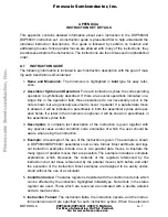
Page 555: ...MOTOROLA DSP56305 User s Manual A 1 APPENDIX A BOOTSTRAP CODE ...

Page 556: ... The accesses will be performed using 31 wait states with no address attributes selected default area If MD MC MB MA 0001 0111 then the bootstrap program jumps to the head of the RTOS ROM address FF0800 The program flow then continues from the RTOS ROM according to the values of MA MB and MC in OMR If MD MC MB MA 1001 then it loads a program RAM segment from consecutive byte wide P memory location...

Page 557: ...ds the program RAM from the Host Interface programmed to operate in the Universal Bus mode supporting 56301 to 56301 glue less connection The HI32 bootstrap code expects first to read a 24 bit word specifying the number of program words afterwards a 24 bit word specifying the address to start loading the program words and then 24 bit word for each program word to be loaded The program words will b...

Page 558: ...T Processor s boot program will verify that the Host Interface is ready by reading the status register HSTR and confirm that TRDY 1 or HTRQ 1 If MD MC MB MA 1100 then it loads the program RAM from the Host Interface programmed to operate in the PCI target slave mode The HI32 bootstrap code expects first to read a 24 bit word specifying the number of program words afterwards a 24 bit word specifyin...

Page 559: ...ee Note below specifying the number of program words afterwards a 24 bit word specifying the address to start loading the program words and then 24 bit word for each program word to be loaded The program words will be stored in contiguous PRAM memory locations starting at the specified starting address After reading the program words program execution starts from the same address where loading sta...

Page 560: ...The number of words the starting address and the program words are received least significant byte first followed by the mid and then by the most significant byte The program words will be condensed into 24 bit words and stored in contiguous PRAM memory locations starting at the specified starting address After reading the program words program execution starts from the same address where loading ...

Page 561: ...E EQU FFFF9F Port E Control register M_DCTR EQU FFFFC5 DSP CONTROL REGISTER DCTR M_DPMC EQU FFFFC7 DSP PCI MASTER CONTROL REGISTER DPMC M_DPAR EQU FFFFC8 DSP PCI ADDRESS REGISTER DPAR M_DSR EQU FFFFC9 DSP STATUS REGISTER DSR M_DRXR EQU FFFFCB DSP RECEIVE DATA FIFO DRXR M_AAR1 EQU FFFFF8 Address Attribute Register 1 ORG PL ff0000 PL ff0000 bootstrap code starts at ff0000 START jclr 3 omr RTOSROM If...

Page 562: ...hrough UB do a0 _LOOP1 Load instruction words do 3 _LOOP2 for each byte _LBLA jset 2 X M_DSR _LBLB Wait for SRRQ to go high i e data ready jclr 3 X M_DSR _LBLA If HF0 1 stop loading new data enddo Must terminate the do loop bra TERMINATE Terminate loop enddo and finish _LBLB movep X M_DRXR a2 Store 16 bit data in accumulator asr 8 a a Shift 8 bit data into A1 _LOOP2 and go get another 24 bit word ...

Page 563: ... data ready movep X M_DRXR A1 Store 24 bit data into A1 and 00ffff A Mask upper byte cmp 37 A Compare the 24 bit dat to 000037 beq _LBLD If dat 37 then go back to loop enddo else break the loop and retry bra _LBLC _LBLD nop _LOOP3 read new CBMA value ISA base address jclr 2 X M_DSR Wait for SRRQ to go high i e data ready movep X M_DRXR A1 Store 24 bit data into A1 Switch to Self Configuration mode...

Page 564: ...ew data bra TERMINATE Terminate loop enddo and finish _LBLF movep X M_DRXR a0 Store 16 bit data in accumulator _LBLG jset 2 X M_DSR _LBLH Wait for SRRQ to go high i e data ready jclr 3 X M_DSR _LBLG If HF0 1 stop loading new data bra TERMINATE Terminate loop enddo and finish _LBLH movep X M_DRXR x0 Store 16 bit data in register _LBLI jset 2 X M_DSR _LBLJ Wait for SRRQ to go high i e data ready jcl...

Page 565: ...lr 0 omr SCILD If MD MC MB MA 1010 go load from SCI If MD MC MB MA 1011 56301 to 56301 boot This is the routine for 56301 to 56301 boot MD MC MB MA 1011 HI32 in UB mode double strobe HTA pin active low UB3HOSTLD movep 268000 x M_DCTR HM 2 UB HIRD 0 HIRQ_ pin open drain HIRH 1 HIRQ_ pin handshake enabled HRSP 1 HRST pin active low HDRP 0 HDRQ pin active high HTAP 1 HTA pin active low HDSM 0 Double ...

Page 566: ... EPROM MD MC MB MA 1001 EPROMLD move BOOT r2 r2 address of external EPROM movep AARV X M_AAR1 aar1 configured for SRAM types of access do 6 _LOOP9 read number of words and starting address movem p r2 a2 Get the 8 LSB from ext P mem asr 8 a a Shift 8 bit data into A1 _LOOP9 move a1 r0 starting address for load move a1 r1 save it in r1 a0 holds the number of words do a0 _LOOP10 read program words do...

Page 567: ...LA DSP56305 User s Manual A 13 expanded mode and jumps to the RESET vector andi 0 ccr Clear CCR as if RESET to 0 jmp r1 Then go to starting Prog addr End of bootstrap code Number of program words 191 dup START 192 nop endm ...

Page 568: ...A 14 DSP56305 User s Manual MOTOROLA Bootstrap Code ...

Page 569: ...Equates MOTOROLA DSP56305 User s Manual B 1 APPENDIX B EQUATES ...

Page 570: ...B 2 DSP56305 User s Manual MOTOROLA Equates B 1 Internal I 0 Equates B 3 B 2 Interrupt Equates B 18 ...

Page 571: ...RRD EQU FFFFAE Port D Direction Data Register M_PDRD EQU FFFFAD Port D GPIO Data Register M_PCRE EQU FFFF9F Port E Control register M_PRRE EQU FFFF9E Port E Direction Register M_PDRE EQU FFFF9D Port E Data Register M_OGDB EQU FFFFFC OnCE GDB Register EQUATES for Host Interface Register Addresses M_DTXS EQU FFFFCD DSP SLAVE TRANSMIT DATA FIFO DTXS M_DTXM EQU FFFFCC DSP MASTER TRANSMIT DATA FIFO DTX...

Page 572: ... EQU 700000 Host Interface Mode Mask Host PCI Control Register Bit Flags M_PMTIE EQU 1 PCI Master Transmit Interrupt Enable M_PMRIE EQU 2 PCI Master Receive Interrupt Enable M_PMAIE EQU 4 PCI Master Address Interrupt Enable M_PPEIE EQU 5 PCI Parity Error Interrupt Enable M_PTAIE EQU 7 PCI Transacton Abort Interrupt Enable M_PTTIE EQU 9 PCI Transaction Term Interrupt Enable M_PTCIE EQU 12 PCI Trans...

Page 573: ...t M_TDIS EQU 9 PCI Target Disconnect M_TRTY EQU 10 PCI Target Retry M_TO EQU 11 PCI Time Out Termination M_RDC EQU 3F0000 Remaining Data Count Mask RDC5 RDC0 M_RDC0 EQU 16 Remaining Data Count 0 M_RDC1 EQU 17 Remaining Data Count 1 M_RDC2 EQU 18 Remaining Data Count 2 M_RDC3 EQU 19 Remaining Data Count 3 M_RDC4 EQU 20 Remaining Data Count 4 M_RDC5 EQU 21 Remaining Data Count 5 M_HACT EQU 23 Hi32 A...

Page 574: ...upt Enable M_SCTIE EQU 12 SCI Transmit Interrupt Enable M_TMIE EQU 13 Timer Interrupt Enable M_TIR EQU 14 Timer Interrupt Rate M_SCKP EQU 15 SCI Clock Polarity M_REIE EQU 16 SCI Error Interrupt Enable REIE SCI Status Register Bit Flags M_TRNE EQU 0 Transmitter Empty M_TDRE EQU 1 Transmit Data Register Empty M_RDRF EQU 2 Receive Data Register Full M_IDLE EQU 3 Idle Line Flag M_OR EQU 4 Overrun Erro...

Page 575: ...er M_CRB1 EQU FFFFA6 SSI1 Control Register B M_CRA1 EQU FFFFA5 SSI1 Control Register A M_TSMA1 EQU FFFFA4 SSI1 Transmit Slot Mask Register A M_TSMB1 EQU FFFFA3 SSI1 Transmit Slot Mask Register B M_RSMA1 EQU FFFFA2 SSI1 Receive Slot Mask Register A M_RSMB1 EQU FFFFA1 SSI1 Receive Slot Mask Register B SSI Control Register A Bit Flags M_PM EQU FF Prescale Modulus Slct Mask PM0 PM7 M_PSR EQU 11 Presca...

Page 576: ...able M_SREIE EQU 23 SSI Receive Error Interrupt Enable SSI Status Register Bit Flags M_IF EQU 3 Serial Input Flag Mask M_IF0 EQU 0 Serial Input Flag 0 M_IF1 EQU 1 Serial Input Flag 1 M_TFS EQU 2 Transmit Frame Sync Flag M_RFS EQU 3 Receive Frame Sync Flag M_TUE EQU 4 Transmitter Underrun Error FLag M_ROE EQU 5 Receiver Overrun Error Flag M_TDE EQU 6 Transmit Data Register Empty M_RDF EQU 7 Receive...

Page 577: ...MA0 Interrupt priority Level Mask M_D0L0 EQU 12 DMA0 Interrupt Priority Level low M_D0L1 EQU 13 DMA0 Interrupt Priority Level high M_D1L EQU C000 DMA1 Interrupt Priority Level Mask M_D1L0 EQU 14 DMA1 Interrupt Priority Level low M_D1L1 EQU 15 DMA1 Interrupt Priority Level high M_D2L EQU 30000 DMA2 Interrupt priority Level Mask M_D2L0 EQU 16 DMA2 Interrupt Priority Level low M_D2L1 EQU 17 DMA2 Inte...

Page 578: ...Level Mask M_VPL0 EQU 12 VCOP Interrupt Priority Level low M_VPL1 EQU 13 VCOP Interrupt Priority Level high M_CPL EQU C000 CCOP Interrupt Priority Level Mask M_CPL0 EQU 14 CCOP Interrupt Priority Level low M_CPL1 EQU 15 CCOP Interrupt Priority Level high EQUATES for TIMER Register Addresses Of TIMER0 M_TCSR0 EQU FFFF8F TIMER0 Control Status Register M_TLR0 EQU FFFF8E TIMER0 Load Reg M_TCPR0 EQU FF...

Page 579: ...scaler Register Bit Flags M_PS EQU 600000 Prescaler Source Mask M_PS0 EQU 21 M_PS1 EQU 22 Timer Control Bits M_TC0 EQU 4 Timer Control 0 M_TC1 EQU 5 Timer Control 1 M_TC2 EQU 6 Timer Control 2 M_TC3 EQU 7 Timer Control 3 EQUATES for Direct Memory Access DMA Register Addresses Of DMA M_DSTR EQU FFFFF4 DMA Status Register M_DOR0 EQU FFFFF3 DMA Offset Register 0 M_DOR1 EQU FFFFF2 DMA Offset Register ...

Page 580: ...f DMA4 M_DSR4 EQU FFFFDF DMA4 Source Address Register M_DDR4 EQU FFFFDE DMA4 Destination Address Register M_DCO4 EQU FFFFDD DMA4 Counter M_DCR4 EQU FFFFDC DMA4 Control Register Register Addresses Of DMA5 M_DSR5 EQU FFFFDB DMA5 Source Address Register M_DDR5 EQU FFFFDA DMA5 Destination Address Register M_DCO5 EQU FFFFD9 DMA5 Counter M_DCR5 EQU FFFFD8 DMA5 Control Register DMA Control Register M_DSS...

Page 581: ...ne Status 3 M_DTD4 EQU 4 DMA Channel Transfer Done Status 4 M_DTD5 EQU 5 DMA Channel Transfer Done Status 5 M_DACT EQU 8 DMA Active State M_DCH EQU E00 DMA Active Channel Mask DCH0 DCH2 M_DCH0 EQU 9 DMA Active Channel 0 M_DCH1 EQU 10 DMA Active Channel 1 M_DCH2 EQU 11 DMA Active Channel 2 EQUATES for Cipher Co Processor CCOP M_CDFR EQU FFFF80 Input output data register FIFO M_CCNT EQU FFFF82 CCOP ...

Page 582: ...trol register A M_VCRB EQU FFFFA3 Viterbi control register B M_VSTR EQU FFFFA4 Viterbi status register M_VCNT EQU FFFFA5 Viterbi data count register M_VTPA EQU FFFFA6 Viterbi tap register A M_VTPB EQU FFFFA7 Viterbi tap register B M_VTSR EQU FFFFA8 Viterbi trellis setup register M_VBER EQU FFFFA9 Viterbi bit error rate register M_VWES EQU FFFFAA Viterbi write only WED setup register M_VWED EQU FFF...

Page 583: ...ss Attribute Register 1 M_AAR2 EQU FFFFF7 Address Attribute Register 2 M_AAR3 EQU FFFFF6 Address Attribute Register 3 M_IDR EQU FFFFF5 ID Register Bus Control Register M_BA0W EQU 1F Area 0 Wait Control Mask BA0W0 BA0W4 M_BA1W EQU 3E0 Area 1 Wait Control Mask BA1W0 BA14 M_BA2W EQU 1C00 Area 2 Wait Control Mask BA2W0 BA2W2 M_BA3W EQU E000 Area 3 Wait Control Mask BA3W0 BA3W3 M_BDFW EQU 1F0000 Defaul...

Page 584: ...erflow M_Z EQU 2 Zero M_N EQU 3 Negative M_U EQU 4 Unnormalized M_E EQU 5 Extension M_L EQU 6 Limit M_S EQU 7 Scaling Bit M_I0 EQU 8 Interupt Mask Bit 0 M_I1 EQU 9 Interupt Mask Bit 1 M_S0 EQU 10 Scaling Mode Bit 0 M_S1 EQU 11 Scaling Mode Bit 1 M_SC EQU 13 Sixteen_Bit Compatibility M_DM EQU 14 Double Precision Multiply M_LF EQU 15 DO Loop Flag M_FV EQU 16 DO Forever Flag M_SA EQU 17 Sixteen Bit A...

Page 585: ... M_BEN EQU 10 Burst Enable M_TAS EQU 11 TA Synchronize Select M_BRT EQU 12 Bus Release Timing M_XYS EQU 16 Stack Extension space select bit in OMR M_EUN EQU 17 Extensed stack UNderflow flag in OMR M_EOV EQU 18 Extended stack OVerflow flag in OMR M_WRP EQU 19 Extended WRaP flag in OMR M_SEN EQU 20 Stack Extension Enable bit in OMR ...

Page 586: ...r I_ILL EQU I_VEC 04 Illegal Instruction I_DBG EQU I_VEC 06 Debug Request I_TRAP EQU I_VEC 08 Trap I_NMI EQU I_VEC 0A Non Maskable Interrupt Interrupt Request Pins I_IRQA EQU I_VEC 10 IRQA I_IRQB EQU I_VEC 12 IRQB I_IRQC EQU I_VEC 14 IRQC I_IRQD EQU I_VEC 16 IRQD DMA Interrupts I_DMA0 EQU I_VEC 18 DMA Channel 0 I_DMA1 EQU I_VEC 1A DMA Channel 1 I_DMA2 EQU I_VEC 1C DMA Channel 2 I_DMA3 EQU I_VEC 1E...

Page 587: ...eceive last slot I_SI1TD EQU I_VEC 46 ESSI1 Transmit data I_SI1TDE EQU I_VEC 48 ESSI1 Transmit Data With Exception Status I_SI1TLS EQU I_VEC 4A ESSI1 Transmit last slot SCI Interrupts I_SCIRD EQU I_VEC 50 SCI Receive Data I_SCIRDE EQU I_VEC 52 SCI Receive Data With Exception Status I_SCITD EQU I_VEC 54 SCI Transmit Data I_SCIIL EQU I_VEC 56 SCI Idle Line I_SCITM EQU I_VEC 58 SCI Timer HOST Interru...

Page 588: ...rbi data out request I_VDONE EQU I_VEC 86 viterbi processing done I_VOPC EQU I_VEC 88 viterbi operation complete CCOP ENCRYPTION Interrupts I_CINFE EQU I_VEC 90 encryption input FIFO empty I_COFNE EQU I_VEC 92 encryption output FIFO not empty I_CCIDN EQU I_VEC 94 encryption processing done I_CPCDN EQU I_VEC 96 encryption parity code processing done INTERRUPT ENDING ADDRESS I_INTEND EQU I_VEC FF la...

Page 589: ...MOTOROLA DSP56305 User s Manual C 1 APPENDIX C JTAG BSDL ...

Page 590: ...C 2 DSP56305 User s Manual MOTOROLA JTAG BSDL ...

Page 591: ...bit SRD0 inout bit SRD1 inout bit SCK1 inout bit STD1 inout bit SC01 inout bit SC11 inout bit SC21 inout bit TXD inout bit SCLK inout bit HINTA_ out bit RXD inout bit TIO0 inout bit TIO1 inout bit TIO2 inout bit HAD inout bit_vector 0 to 31 HBE inout bit_vector 0 to 3 HGNT_ in bit HCLK in bit HRST_ in bit HREQ_ out bit HPAR inout bit HSERR_ out bit HPERR_ inout bit HLOCK_ inout bit HSTOP_ inout bi...

Page 592: ...ED linkage bit_vector 0 to 7 SGND linkage bit_vector 0 to 1 SVCC linkage bit_vector 0 to 1 QGND linkage bit_vector 0 to 3 QVCC linkage bit_vector 0 to 3 HGND linkage bit_vector 0 to 5 HVCC linkage bit_vector 0 to 5 DGND linkage bit_vector 0 to 3 DVCC linkage bit_vector 0 to 3 AGND linkage bit_vector 0 to 5 AVCC linkage bit_vector 0 to 5 NGND linkage bit_vector 0 to 1 NVCC linkage bit_vector 0 to 1...

Page 593: ...3 49 57 63 AVCC 32 38 44 50 58 64 RESERVED 53 54 103 104 157 158 207 208 D 67 68 69 72 73 74 75 76 77 82 83 84 85 86 87 90 91 92 93 94 95 98 99 100 DGND 70 80 88 96 DVCC 71 81 89 97 IRQA_ 101 IRQB_ 102 IRQC_ 105 IRQD_ 106 HAD 173 172 171 170 167 166 165 164 162 161 160 159 154 153 152 151 127 126 125 124 121 120 119 118 116 115 114 113 110 109 108 107 HVCC 135 144 156 169 111 122 HGND 136 143 155 ...

Page 594: ...00 196 SC10 197 SC20 198 DE_ 199 TMS 200 TCK 201 TDI 202 TDO 203 TRST_ 204 BS_ 205 BL_ 206 attribute TAP_SCAN_IN of TDI signal is true attribute TAP_SCAN_OUT of TDO signal is true attribute TAP_SCAN_MODE of TMS signal is true attribute TAP_SCAN_RESET of TRST_ signal is true attribute TAP_SCAN_CLOCK of TCK signal is 20 0e6 BOTH attribute INSTRUCTION_LENGTH of DSP56305 entity is 4 attribute INSTRUCT...

Page 595: ..._ output3 X 7 1 Z 1 BC_2 BL_ output2 X 2 BC_1 AA 0 output3 X 4 1 Z 3 BC_1 AA 1 output3 X 5 1 Z 4 BC_1 control 1 5 BC_1 control 1 6 BC_1 control 1 7 BC_1 control 1 8 BC_2 CLKOUT output2 X 9 BC_1 BCLK output3 X 7 1 Z 10 BC_1 CAS_ output3 X 6 1 Z 11 BC_2 TA_ input X 12 BC_2 PINIT input X 13 BC_2 RES_ input X 14 BC_6 BB_ bidir X 17 1 Z 15 BC_2 BG_ input X 16 BC_2 BR_ output2 X 17 BC_1 control 1 18 BC_...

Page 596: ...1 output3 X 45 1 Z 50 BC_1 A 22 output3 X 45 1 Z 51 BC_1 A 23 output3 X 45 1 Z 52 BC_6 D 0 bidir X 55 1 Z 53 BC_6 D 1 bidir X 55 1 Z 54 BC_6 D 2 bidir X 55 1 Z 55 BC_1 control 1 56 BC_6 D 3 bidir X 55 1 Z 57 BC_6 D 4 bidir X 55 1 Z 58 BC_6 D 5 bidir X 55 1 Z 59 BC_6 D 6 bidir X 55 1 Z num cell port func safe ccell dis rslt 60 BC_6 D 7 bidir X 55 1 Z 61 BC_6 D 8 bidir X 55 1 Z 62 BC_6 D 9 bidir X 5...

Page 597: ...X 98 1 Z num cell port func safe ccell dis rslt 100 BC_1 control 1 101 BC_6 HAD 23 bidir X 100 1 Z 102 BC_1 control 1 103 BC_6 HAD 22 bidir X 102 1 Z 104 BC_1 control 1 105 BC_6 HAD 21 bidir X 104 1 Z 106 BC_1 control 1 107 BC_6 HAD 20 bidir X 106 1 Z 108 BC_1 control 1 109 BC_6 HAD 19 bidir X 108 1 Z 110 BC_1 control 1 111 BC_6 HAD 18 bidir X 110 1 Z 112 BC_1 control 1 113 BC_6 HAD 17 bidir X 112...

Page 598: ...l 1 147 BC_6 HAD 14 bidir X 146 1 Z 148 BC_1 control 1 149 BC_6 HAD 13 bidir X 148 1 Z 150 BC_1 control 1 151 BC_6 HAD 12 bidir X 150 1 Z 152 BC_1 control 1 153 BC_6 HAD 11 bidir X 152 1 Z 154 BC_1 control 1 155 BC_6 HAD 10 bidir X 154 1 Z 156 BC_1 control 1 157 BC_6 HAD 9 bidir X 156 1 Z 158 BC_1 control 1 159 BC_6 HAD 8 bidir X 158 1 Z num cell port func safe ccell dis rslt 160 BC_1 control 1 16...

Page 599: ...ontrol 1 192 BC_6 SC21 bidir X 191 1 Z 193 BC_1 control 1 194 BC_6 SC11 bidir X 193 1 Z 195 BC_1 control 1 196 BC_6 SC01 bidir X 195 1 Z 197 BC_1 control 1 198 BC_6 STD1 bidir X 197 1 Z 199 BC_1 control 1 num cell port func safe ccell dis rslt 200 BC_6 SCK1 bidir X 199 1 Z 201 BC_1 control 1 202 BC_6 SRD1 bidir X 201 1 Z 203 BC_1 control 1 204 BC_6 SRD0 bidir X 203 1 Z 205 BC_1 control 1 206 BC_6 ...

Page 600: ...C 12 DSP56305 User s Manual MOTOROLA JTAG BSDL ...

Page 601: ...MOTOROLA DSP56305 User s Manual D 1 APPENDIX D PROGRAMMING REFERENCE ...

Page 602: ...D 2 DSP56305 User s Manual MOTOROLA PROGRAMMING REFERENCE ...

Page 603: ...bit and the hexadecimal value for each register The programmer can photocopy these sheets and reuse them for each application development project For details on the instruction set of the DSP56300 family chips see the DSP56300 Family Manual D 1 1 Peripheral Addresses Table D 1 lists the memory addresses of all on chip peripherals D 1 2 Interrupt Addresses Table D 2 lists the interrupt starting add...

Page 604: ...FFA FFFFFA DRAM Control Register DCR FFF9 FFFFF9 Address Attribute Register 0 AAR0 FFF8 FFFFF8 Address Attribute Register 1 AAR1 FFF7 FFFFF7 Address Attribute Register 2 AAR2 FFF6 FFFFF6 Address Attribute Register 3 AAR3 FFF5 FFFFF5 ID Register IDR DMA FFF4 FFFFF4 DMA Status Register DSTR FFF3 FFFFF3 DMA Offset Register 0 DOR0 FFF2 FFFFF2 DMA Offset Register 1 DOR1 FFF1 FFFFF1 DMA Offset Register ...

Page 605: ...3 FFE3 FFFFE3 DMA Source Address Register DSR3 FFE2 FFFFE2 DMA Destination Address Register DDR3 FFE1 FFFFE1 DMA Counter DCO3 FFE0 FFFFE0 DMA Control Register DCR3 DMA4 FFDF FFFFDF DMA Source Address Register DSR4 FFDE FFFFDE DMA Destination Address Register DDR4 FFDD FFFFDD DMA Counter DCO4 FFDC FFFFDC DMA Control Register DCR4 DMA5 FFDB FFFFDB DMA Source Address Register DSR5 FFDA FFFFDA DMA Des...

Page 606: ... Reserved FFCA FFFFCA Reserved PORT B FFC9 FFFFC9 Host Port GPIO Data Register HDR FFC8 FFFFC8 Host Port GPIO Direction Register HDDR HI08 FFC7 FFFFC7 Host Transmit Register HTX FFC6 FFFFC6 Host Receive Register HRX FFC5 FFFFC5 Host Base Address Register HBAR FFC4 FFFFC4 Host Polarity Control Register HPCR FFC3 FFFFC3 Host Status Register HSR FFC2 FFFFC2 Host Control Register HCR FFC1 FFFFC1 Reser...

Page 607: ...Data Register RX0 FFB7 FFFFB7 ESSI 0 Status Register SSISR0 FFB6 FFFFB6 ESSI 0 Control Register B CRB0 FFB5 FFFFB5 ESSI 0 Control Register A CRA0 FFB4 FFFFB4 ESSI 0 Transmit Slot Mask Register A TSMA0 FFB3 FFFFB3 ESSI 0 Transmit Slot Mask Register B TSMB0 FFB2 FFFFB2 ESSI 0 Receive Slot Mask Register A RSMA0 FFB1 FFFFB1 ESSI 0 Receive Slot Mask Register B RSMB0 FFB0 FFFFB0 Reserved PORT D FFAF FFF...

Page 608: ...FFA6 ESSI 1 Control Register B CRB1 FFA5 FFFFA5 ESSI 1 Control Register A CRA1 FFA4 FFFFA4 ESSI 1 Transmit Slot Mask Register A TSMA1 FFA3 FFFFA3 ESSI 1 Transmit Slot Mask Register B TSMB1 FFA2 FFFFA2 ESSI 1 Receive Slot Mask Register A RSMA1 FFA1 FFFFA1 ESSI 1 Receive Slot Mask Register B RSMB1 FFA0 FFFFA0 Reserved PORT E FF9F FFFF9F Port E Control Register PCRE FF9E FFFF9E Port E Direction Regis...

Page 609: ...M FF98 FFFF98 SCI Recieve Data Register Low SRXL FF97 FFFF97 SCI Transmit Data Register High STXH FF96 FFFF96 SCI Transmit Data Register Middle STXM FF95 FFFF95 SCI Transmit Data Register Low STXL FF94 FFFF94 SCI Transmit Address Register STXA FF93 FFFF93 SCI Status Register SSR FF92 FFFF92 Reserved FF91 FFFF91 Reserved FF90 FFFF90 Reserved Table D 1 Internal I O Memory Map Continued Peripheral 16...

Page 610: ... 1 Load Register TLR1 FF89 FFFF89 Timer 1 Compare Register TCPR1 FF88 FFFF88 Timer 1 Count Register TCR1 FF87 FFFF87 Timer 2 Control Status Register TCSR2 FF86 FFFF86 Timer 2 Load Register TLR2 FF85 FFFF85 Timer 2 Compare Register TCPR2 FF84 FFFF84 Timer 2 Count Register TCR2 FF83 FFFF83 Timer Prescaler Load Register TPLR FF82 FFFF82 Timer Prescaler Count Register TPCR FF81 FFFF81 Reserved FF80 FF...

Page 611: ... 0C 3 Reserved VBA 0E 3 Reserved VBA 10 0 2 IRQA VBA 12 0 2 IRQB VBA 14 0 2 IRQC VBA 16 0 2 IRQD VBA 18 0 2 DMA Channel 0 VBA 1A 0 2 DMA Channel 1 VBA 1C 0 2 DMA Channel 2 VBA 1E 0 2 DMA Channel 3 VBA 20 0 2 DMA Channel 4 VBA 22 0 2 DMA Channel 5 VBA 24 0 2 TIMER 0 Compare VBA 26 0 2 TIMER 0 Overflow VBA 28 0 2 TIMER 1 Compare VBA 2A 0 2 TIMER 1 Overflow VBA 2C 0 2 TIMER 2 Compare VBA 2E 0 2 TIMER...

Page 612: ...a With Exception Status VBA 4A 0 2 ESSI1 Transmit Last Slot VBA 4C 0 2 Reserved VBA 4E 0 2 Reserved VBA 50 0 2 SCI Receive Data VBA 52 0 2 SCI Receive Data With Exception Status VBA 54 0 2 SCI Transmit Data VBA 56 0 2 SCI Idle Line VBA 58 0 2 SCI Timer VBA 5A 0 2 Reserved VBA 5C 0 2 Reserved VBA 5E 0 2 Reserved VBA 60 0 2 Host Receive Data Full VBA 62 0 2 Host Transmit Data Empty VBA 64 0 2 Host C...

Page 613: ...Debug Request Interrupt Trap Lowest Non Maskable Interrupt Levels 0 1 2 Maskable Highest IRQA External Interrupt IRQB External Interrupt IRQC External Interrupt IRQD External Interrupt DMA Channel 0 Interrupt DMA Channel 1 Interrupt DMA Channel 2 Interrupt DMA Channel 3 Interrupt DMA Channel 4 Interrupt DMA Channel 5 Interrupt Host Command Interrupt Host Transmit Data Empty Host Receive Data Full ...

Page 614: ...ESSI1 Receive Last Slot Interrupt ESSI1 TX Data With Exception Interrupt ESSI1 Transmit Last Slot Interrupt ESSI1 TX Data Interrupt SCI Receive Data With Exception Interrupt SCI Receive Data SCI Transmit Data SCI Idle Line SCI Timer TIMER0 Overflow Interrupt TIMER0 Compare Interrupt TIMER1 Overflow Interrupt TIMER1 Compare Interrupt TIMER2 Overflow Interrupt Lowest TIMER2 Compare Interrupt Table D...

Page 615: ... DMA channel 2 00111 Transfer Done from DMA channel 3 01000 Transfer Done from DMA channel 4 01001 Transfer Done from DMA channel 5 01010 ESSI0 Receive Data RDF0 1 01011 ESSI0 Transmit Data TDE0 1 01100 ESSI1 Receive Data RDF1 1 01101 ESSI1 Transmit Data TDE1 1 01110 SCI Receive Data RDRF 1 01111 SCI Transmit Data TDRE 1 10000 Timer0 TCF0 1 10001 Timer1 TCF1 1 10010 Timer2 TCF2 1 10011 FCOP Data I...

Page 616: ...rovide a set of programming reference sheets for the DSP56305 registers 11000 VCOP Processing Done DONE 1 11001 CCOP Input FIFO Empty INFE 1 11010 CCOP Cipher Processing Done CIDN 1 11011 Reserved 11100 Host Slave Receive Data SRRQ 1 11101 Host Master Receive Data MRRQ 1 11110 Host Slave Transmit Data STRQ 1 11111 Host Master Transmit Data MTRQ 1 DMA Request Source Bits DRS4 DRS0 Requesting Device...

Page 617: ...asked 00 01 10 11 None IPL 0 IPL 0 1 IPL 0 1 2 Carry Over ow Zero Negative Unnormalized U Acc 47 xnor Acc 46 Extension Limit FFT Scaling S Acc 46 xor Acc 45 Reserved Sixteen Bit Compatibilitity Double Precision Multiply Mode Loop Flag DO Forever Flag Sixteenth Bit Arithmetic Reserved Instruction Cache Enable Arithmetic Saturation Rounding Mode Core Priority CP 1 0 Core Priority 00 01 10 11 0 lowes...

Page 618: ...BD MC MB MA 19 18 17 16 23 22 21 20 SD BRT TAS SEN CDP1 CDP0 WRP EOV EUN XYS BE MD Core DMA Priority CDP 1 0 Core DMA Priority 00 01 10 11 Core vs DMA Priority DMA accesses Core DMA accesses Core DMA accesses Core 0 0 0 0 Chip Operating Mode Register COM System Stack Control Status Register SCS Extended Chip Operating Mode Register COM X Latched from levels on Mode pins Operating Mode Register OMR...

Page 619: ...00 Register IPR C 23 22 21 20 19 18 16 17 D1L1 IAL2 Trigger 0 Level 1 Neg Edge IRQA Mode IAL1 IAL0 Enabled IPL 0 0 No 0 1 Yes 0 1 0 Yes 1 1 1 Yes 2 IBL2 Trigger 0 Level 1 Neg Edge IRQB Mode IBL1 IBL0 Enabled IPL 0 0 No 0 1 Yes 0 1 0 Yes 1 1 1 Yes 2 ICL0 ICL1 ICL2 IDL0 D2L0 D2L1 D3L0 D3L1 D4L0 D4L1 D5L0 D5L1 ICL2 Trigger 0 Level 1 Neg Edge IRQC Mode ICL1 ICL0 Enabled IPL 0 0 No 0 1 Yes 0 1 0 Yes 1 ...

Page 620: ...abled IPL 0 0 No 0 1 Yes 0 1 0 Yes 1 1 1 Yes 2 Host IPL S0L1 S0L0 Enabled IPL 0 0 No 0 1 Yes 0 1 0 Yes 1 1 1 Yes 2 ESSI0 IPL 15 14 13 12 11 10 9 8 7 6 5 4 3 2 1 0 S1L1 S1L0 SOL1 S0L0 HPL1 HPL0 23 22 21 20 19 18 16 17 SCL0 SCL1 T0L0 T0L1 0 0 0 0 0 0 0 0 0 0 0 0 0 0 0 0 0 S1L1 S1L0 Enabled IPL 0 0 No 0 1 Yes 0 1 0 Yes 1 1 1 Yes 2 ESSI1 IPL SCL1 SCL0 Enabled IPL 0 0 No 0 1 Yes 0 1 0 Yes 1 1 1 Yes 2 S...

Page 621: ...al Source Clock Output Disable COD 0 50 Duty Cycle Clock 1 Pin Held In High State Crystal Range Bit XTLR 0 External Xtal Freq 200KHz 1 External Xtal Freq 200KHz Predivision Factor Bits PD0 PD3 PD3 PD0 Predivision Factor PDF 0 1 2 F 1 2 3 16 Multiplication Factor Bits MF0 MF11 MF11 MF0 Multiplication Factor MF 000 001 002 FFE FFF 1 2 3 4095 4096 Division Factor Bits DF0 DF2 DF2 DF0 Division Factor ...

Page 622: ...9 18 17 16 23 22 21 20 Receive High Byte Receive Middle Byte Receive Low Byte Host Receive Data Register HRX X FFEC6 Read Only Reset empty Host Receive Data usually Read by program 15 14 13 12 11 10 9 8 7 6 5 4 3 2 1 0 19 18 17 16 23 22 21 20 Transmit High Byte Transmit Middle Byte Transmit Low Byte Host Transmit Data usually Loaded by program Host Transmit Data Register HTX X FFEC7 Write Only Res...

Page 623: ...E HF0 Host Flags Read Only Host Command Pending 1 Ready 0 Wait Host Transmit Data Empty 1 Write 0 Wait 0 Host Staus Register HSR X FFFFC3 Read Only Reset 2 7 6 5 4 3 2 1 0 15 0 0 0 Host Receive Interrupt Enable 1 Enable 0 Disable HCIE HRIE HF3 HTIE HF2 Host Flag 2 Host Command Interrupt Enable Host Transmit Interrupt Enable 1 Enable 0 Disable 0 Host Control Register HCR X FFFFC2 Read Write Reset 0...

Page 624: ...UX 1 Host Address Line 9 Enable 0 HA9 GPIO 1 HA9 HA9 Host Address Line 8 Enable 0 HA8 GPIO 1 HA8 HA8 Host GPIO Port Enable 0 GPIO Pins Disable 1 GPIO Pin Enable Host Acknowledge Priority 0 HACK Active Low 1 HACK Active High Host Chip Select Polarity 0 HCS Active Low Host Dual Data Strobe 0 Singles Stroke 1 Dual Stoke Host Multiplexed Bus 0 Nonmultiplexed 1 Multiplexed Host Address Strobe Polarity ...

Page 625: ...Initialize Write Only Host Little Endian Receive Request Enable DMA Off 0 Interrupts Disabled 1 Interrupts Enabled DMA On 0 Host DSP 1 DSP Host 0 No Action 1 Initialize DMA HDRQ 0 HDRQ HREQ HTRQ HACK HRRQ 0 HREQ HACK 1 HTRQ HRRQ Reset 0 7 6 5 4 3 2 1 0 Reserved Program as 0 0 RXDF HF3 TXDE HF2 HREQ DMA TRDY Interrupt Status Register ISR 2 Read Write Reset 06 Transmit Data Register Empty 0 Wait 1 W...

Page 626: ... 7 6 5 4 3 2 1 0 IV0 IV4 IV1 IV3 IV7 IV5 Interrupt Vector Register IVR IV2 Reset 0F Contains the interrupt vector or number IV6 7 6 5 4 3 2 1 0 HC0 HC4 HC1 HC3 HC7 HC5 Command Vector Register CVR HC2 Reset 2A Contains the host command interrupt address HC6 Host Vector Contains Host Command Interrupt Address 2 Host Command Handshakes Executing Host Command Interrupts ...

Page 627: ...ceive Data usually Read by program Receive Byte Registers 7 6 5 4 Read Only Reset 00 Transmit Byte Registers 7 6 5 4 Write Only Reset 00 Receive Byte Registers 6 5 4 0 0 0 0 0 0 0 0 0 7 7 Receive Middle Byte Receive High Byte Not Used Receive Low Byte 7 0 7 0 0 7 Host Transmit Data usually loaded by program 6 5 4 0 0 0 0 0 0 0 0 0 7 7 Transmit Middle Byte Transmit High Byte Not Used Transmit Low B...

Page 628: ...rst 24 bits 1 0 1 32 data in last 24 bits 1 1 0 Reserved 1 1 1 Reserved ESSI Control Register A CRAx ESSI0 FFFFB5 Read Write ESSI1 FFFFA5 Read Write Reset 000000 Select SC1 as Tx 0 drive enable 0 SC1 functions as serial I O flag 1 functions as driver enable of Tx 0 external buffer Frame Rate Divider Control DC4 0 00 1F 1 to 32 Divide ratio for Normal mode of time slots for Network Prescaler Range ...

Page 629: ...ut on rising in on falling 1 in on rising out on falling Sync Async Control Tx Rx transfer together or not 0 Asynchronous 1 Synchronous ESSI Control Register B CRBx ESSI0 FFFFB6 Read Write ESSI1 FFFFA6 Read Write Reset 000000 Transmit 1 Enable SYN 1 only 0 Disable 1 Enable Transmit Interrupt Enable 0 Disable 1 Enable Receive Interrupt Enable 0 Disable 1 Enable Transmit Last Slot Interrupt Enable 0...

Page 630: ...Wait 1 Frame Sync Occurred Transmitter Underrun Error Flag 0 OK 1 Error Receiver Overrun Error Flag 0 OK 1 Error Transmit Data Register Empty 0 Wait 1 Write Transmit Frame Sync 0 Sync Inactive 1 Sync Active Receive Data Register Full 1 Read Serial Input Flag 0 If SCD0 0 SYN 1 TE1 0 latch SC0 on FS Serial Input Flag 1 If SCD1 0 SYN 1 TE2 0 latch SC0 on FS 0 Wait SSI Status Bits SSI Status Register ...

Page 631: ...rite ESSI1 FFFFA3 Read Write Reset FFFF ESSI Receive Slot Mask A ESSI Receive Slot Mask B ESSI Transmit Slot Mask A ESSI Transmit Slot Mask B 15 14 13 12 11 10 9 8 7 6 5 4 3 2 1 0 RS7 RS5 RS4 RS3 RS2 RS1 RS0 16 23 Reserved Program as 0 RS6 0 RS15 RS14 RS13 RS12 RS11 15 14 13 12 11 10 9 8 7 6 5 4 3 2 1 0 TS23 TS21 TS20 TS19 TS18 TS17 TS16 16 23 Reserved Program as 0 TS22 0 TS31 TS30 TS29 TS28 TS27 ...

Page 632: ...lect Bits 0 0 0 8 bit Synchronous Data Shift Register Mode 0 0 1 Reserved 0 1 0 10 bit Asynchronous 1 Start 8 Data 1 Stop 0 1 1 Reserved 1 0 0 11 bit Asynchronous 1 Start 8 Data Even Parity 1 Stop 1 0 1 11 bit Asynchronous 1 Start 8 Data Odd Parity 1 Stop 1 1 0 11 bit Multidrop 1 Start 8 Data Data Type 1 Stop 1 1 1 Reserved Port E Control Register PCRE X FFFF9F Read Write Reset 000000 Transmitter ...

Page 633: ...egister Full 0 Receive Data Register Full 1 Receive Data Register Empty Transmitter Data Register Empty 0 Transmitter Data Register full 1 Transmitter Data Register empty Transmitter Empty 0 Transmitter full 1 Transmitter empty Clock Divider Bits CD11 CD0 CD11 CD0 Icyc Rate 000 Icyc 1 001 Icyc 2 002 Icyc 3 FFE Icyc 4095 FFF Icyc 4096 SCI Clock Prescaler 0 1 1 8 SCI Status Register SSR Clock Out Di...

Page 634: ... Registers Address X FFFF95 X FFFF97 Write Reset xxxxxx Unpacking TXD SCI Transmit SR SCI Transmit Data Registers SCI Receive Data Registers X FFFF94 STXA 23 16 15 8 7 0 SRX SRX SRX A B C Packing RXD SCI Receive SR SCI Receive Data Registers Address X FFFF98 X FFFF9A Read Reset xxxxxx X FFFF9A X FFFF99 X FFFF98 Note STX is the same register decoded at four different addresses Note STX is the same ...

Page 635: ...6 23 22 21 20 PS0 PS1 0 Prescaler Preload Value PL 0 20 Reserved Program as 0 15 14 13 12 11 10 9 8 7 6 5 4 3 2 1 0 19 18 17 16 23 22 21 20 0 Current Value of Prescaler Counter PC 0 20 Timer Prescaler Load Register TPLR FFFF83 Read Write Reset 000000 Timer Prescaler Count Register TPCR FFFF82 Read Only Reset 000000 Reserved Program as 0 PS 1 0 Prescaler Clock Source 00 Internal CLK 2 01 TIO0 10 TI...

Page 636: ...Control Bits 4 7 TC0 TC3 TC 3 0 TIO Clock Mode 0000 0001 0010 0011 0100 0101 0110 0111 1000 1001 1010 1011 1100 1101 1110 1111 GPIO Output Output Input Input Input Input Output Output Output Internal Internal Internal External Internal Internal Internal Internal Internal Internal Timer Timer Pulse Timer Toggle Event Counter Input Width Input Period Capture Pulse Width Modulation Reserved Watchdog ...

Page 637: ...er TLR0 FFFF8E Write Only Reset 000000 TLR1 FFFF8A Write Only TLR2 FFFF86 Write Only Timer Compare Register TCPR0 FFFF8D Read Write Reset 000000 TCPR1 FFFF89 Read Write TCPR2 FFFF85 Read Write Timer Count Register TCR0 FFFF8C Read Only TCR1 FFFF88 Read Only TCR2 FFFF84 Read Only Reset 000000 15 14 13 12 11 10 9 8 7 6 5 4 3 2 1 0 19 18 17 16 23 22 21 20 Value Compared to Counter Value 15 14 13 12 1...

Page 638: ... 2 1 0 DR5 DR4 DR3 DR2 DR1 DR0 DR6 DR15 DR14 DR13 DR12 DR8 DR11 DR9 DR10 Direction Register X FFFFC8 Reset 0 HDDR Write Host Data DRx 0 HIx is Input DRx 1 HIx is Output 15 14 13 12 11 10 9 8 7 6 5 4 3 2 1 0 D5 D4 D3 D2 D1 D0 D6 D15 D14 D13 D12 D8 D11 D9 D10 Register X FFFFC9 Reset Undefined HDR Write Host Data DRx holds value of corresponding HI08 GPIO pin DR7 D7 Function depends on HDDR Port B HI...

Page 639: ...t Pin configured as ESSI PCn 0 Port Pin configured as GPIO Port C ESSI0 23 6 5 4 3 2 1 0 PDC5 PDC4 PDC3 PDC2 PDC1 PDC0 Port C Direction Register X FFFFBE Reset 0 PRRC ReadWrite 0 0 PDCn 1 Port Pin is Output PDCn 0 Port Pin is Input 23 6 5 4 3 2 1 0 PD5 PD4 PD3 PD2 PD1 PD0 Port C GPIO Data Register X FFFFBD Reset 0 PDRC ReadWrite 0 0 port pin n is GPIO input then PDn reflects the value on port pin ...

Page 640: ...t Pin configured as ESSI PCn 0 Port Pin configured as GPIO Port D ESSI1 23 6 5 4 3 2 1 0 PDC5 PDC4 PDC3 PDC2 PDC1 PDC0 Port D Direction Register X FFFFAE Reset 0 PRRD ReadWrite 0 0 PDCn 1 Port Pin is Output PDCn 0 Port Pin is Input 23 6 5 4 3 2 1 0 PD5 PD4 PD3 PD2 PD1 PD0 Port D GPIO Data Register X FFFFAD Reset 0 PDRD ReadWrite 0 0 port pin n is GPIO input then PDn reflects the value on port pin ...

Page 641: ...nfigured as SCI PCn 0 Port Pin configured as GPIO Port E SCI 23 6 5 4 3 2 1 0 PDC2 PDC1 PDC0 Port E Direction Register X FFFF9E Reset 0 PRRE ReadWrite 0 0 PDCn 1 Port Pin is Output PDCn 0 Port Pin is Input 23 6 5 4 3 2 1 0 PD2 PD1 PD0 Port E GPIO Data Register X FFFF9D Reset 0 PDRE ReadWrite 0 0 port pin n is GPIO input then PDn reflects the value on port pin n if port pin n is GPIO output then va...

Page 642: ...D 42 DSP56305 User s Manual MOTOROLA PROGRAMMING REFERENCE D 7 QUICK REFERENCE TABLES See Table D 5 HI32 Programming Model Quick Reference on page D 43 ...

Page 643: ...ata strobe HRW HDS single data strobe may be changed only in PS reset 0 HRWP Host RD WR Polarity 0 1 HRW 0 WRITE 1 READ HRW 0 READ 1 WRITE may be changed only in PS reset 0 HTAP Host Transfer Acknowledge Polarity 0 1 HTA HTA may be changed only in PS reset 0 HDRP Host DMA Request Polarity 0 1 HDRQ HDRQ may be changed only in PS reset 0 HRSP Host Reset Polarity 0 1 HRST HRST may be changed only in ...

Page 644: ... Clear Transmitter 0 1 inactive empty master transmitter path may be set only if MARQ 1 cleared by hardware 0 MTT Master Transfer Terminate 0 1 inactive terminate current PCI transaction may be set only if MWS 1 cleared by hardware 0 SERF HSERR Force 0 1 inactive generate a PCI system error cleared by hardware 0 18 MACE Master Access Counter Enable 0 1 unlimited burst length burst length is limite...

Page 645: ... if MARQ 1 0 23 20 BE3 BE0 PCI Byte Enables may be written only if MARQ 1 0 DSR HCP Host Command Pending 0 1 no host command pending host command pending cleared when the HC interrupt request is serviced 0 STRQ Slave Transmit Data Request 1 0 slave transmit FIFO is not full slave transmit FIFO is full cleared if the DTXS is filled by core writes 1a 1 a SRRQ Slave Receive Data Request 0 1 slave rec...

Page 646: ... not occurred a data parity error has occurred cleared by writing 1 0 MAB PCI Master Abort 0 1 a master abort has not occurred a master abort has occurred cleared by writing 1 0 TAB PCI Target Abort 0 1 a target abort has not occurred a target abort has occurred cleared by writing 1 0 TDIS PCI Target Disconnect 0 1 a target disconnect has not occurred a target disconnect has occurred cleared by wr...

Page 647: ...ISA 0 1 HI32 does not support DMA transfers HI32 supports ISA DMA type transfers 0 7 SFT Slave Fetch Type 0 1 Pre fetch Fetch 0 9 8 HTF1 HTF0 Host Transmit Data Transfer Format 00 01 10 11 PCI UB 32 bit mode24 bit mode 3 LSBs2 Right zero ext 3 LSBs2 Right sign ext 3 MSbs2 Left zero filled 0 12 11 HRF1 HRF 0 Host Receive Data Transfer Format 00 01 10 11 PCI UB 32 bit mode24 bit mode 3 Right zero ex...

Page 648: ...RQ signal is asserted if enabled 0 HCVR 0 HC Host Command 0 1 no host command pending host command pending cleared when the HC interrupt request is serviced 0 7 1 HV6 HV0 Host Command Vector default vector via programm able Section 6 10 default vector 15 HNMI Host Non Maskable Int Req 0 1 a maskable interrupt request a non maskable interrupt request 0 HRXM 31 0 Host Master Receive Data FIFO empty ...

Page 649: ...SEL Timing 01 medium DEVSEL timing hardwired 01 27 STA Signaled Target Abort 0 1 HI32 has not generated a target abort event HI32 target generated a target abort event cleared by writing 1 0 28 RTA Received Target Abort 0 1 HI32 has not received a target abort event HI32 master received a target abort event cleared by writing 1 0 29 RMA Received Master Abort 0 1 HI32 has not received a master abor...

Page 650: ... 15 4 PM15 PM4 Memory Base Address Low 00 64Kbytes occupancy of PCI memory space hardwired 00 31 16 PM31 PM1 6 Memory Base Address High 0000 23 15 GB10 GB3 Genbus Base Address 00 CILP 7 0 IP 7 IP0 Interrupt Signal PCI interrupt line routing information 15 8 IL7 IL0 Interrupt Line 01 INTA is supported hardwired 01 23 16 MG7 MG0 MAX_GNT 00 Min Grant hardwired 00 31 24 ML7 ML0 MAX_LAT 00 Max Latency ...

Page 651: ...ck 2 8 clock 1 7 Clock Divider bits CD0 CD11 8 18 Clock Generator CLKGEN 1 11 Clock Out Divider bit COD 8 18 Clock Polarity bit CKP 7 24 Clock Source Direction bit SCKD 7 22 CMOS 1 7 COD bit 8 18 code compatible 1 7 Core Status bits OS0 OS1 10 9 CRA register 7 15 bits 0 7 Prescale Modulus Select bits PM0 PM7 7 15 bits 8 10 reserved bits 7 15 bit 11 Prescaler Range bit PSR 7 15 bit 17 reserved bit ...

Page 652: ... Interface ESSI 1 16 ESSI 2 3 2 4 2 29 2 32 after reset 7 43 asynchronous operating mode 7 50 frame sync length 7 51 frame sync polarity 7 52 frame sync selection 7 51 frame sync word length 7 51 GPIO functionality 7 53 initialization 7 43 interrupts 7 45 Network mode 7 48 Normal mode 7 48 operating mode 7 43 operating modes 7 48 Port Control Register PCR 7 54 Port Data Register PDR 7 56 Port Dire...

Page 653: ...n 11 11 Host Inteface 2 3 Host Interface 1 16 2 4 2 18 2 19 PCI 2 4 PCI bus 2 5 universal bus 2 5 host port configuration 2 18 usage considerations 2 18 I IDCODE instruction 11 9 IDLE bit 8 15 Idle Line Flag bit IDLE 8 15 Idle Line Interrupt Enable bit ILIE 8 12 IF0 bit 7 35 IF1 bit 7 36 ILIE bit 8 12 IME bit 10 8 instruction cache 3 3 location 3 10 instruction set 1 7 internal buses 1 13 interrup...

Page 654: ... 10 15 OCR register bits 0 4 Register Select bits RS0 RS4 10 6 bit 5 Exit Command bit EX 10 6 bit 6 GO Command bit GO 10 6 bit 7 Read Write Command bit R W 10 6 ODEC 10 8 OF0 OF1 bits 7 20 offset adder 1 9 OGDBR register 10 20 OMAC0 comparator 10 11 OMAC1 comparator 10 11 OMAL register 10 11 OMBC counter 10 14 OMLR0 register 10 11 OMLR1 register 10 11 OMR bit 15 Address Tracing Enable bit ATE 4 22...

Page 655: ...OS1 10 9 reserved bits bits 8 23 10 10 OTC counter 10 16 Overrun Error Flag bit OR 8 15 P PAB 1 13 PAG 1 10 Parity Error bit PE 8 16 Patch Mode PEN bit 4 23 PC register 1 10 PC0 PC20 bits 9 7 PCE bit 9 16 PCRC register 7 54 PCRD register 7 54 PCRE register 8 29 PCTL register bits 0 11 Multiplication Factor bits MF0 MF11 4 23 bit 16 XTAL Disable bit XTLD 4 24 bits 20 23 PreDivider Factor bits PD0 P...

Page 656: ...errupt Enable bit RIE 7 34 8 13 Receive Last Slot Interrupt Enable bit RLIE 7 34 Receive Shift Register 7 40 Receive Slot Mask Registers RSMA RSMB 7 42 Received Bit 8 Address bit R8 8 16 Receiver Enable bit RE 8 11 Receiver Overrun Error Flag bit ROE 7 37 Receiver Wakeup Enable bit SBK 8 11 Register Select bits RS0 RS4 10 6 REIE bit 7 35 8 14 reserved bits in CRA register 7 15 7 18 7 19 in OBCR re...

Page 657: ...1 bit 9 Transmitter Enable bit TE 8 12 bit 10 Idle Line Interrupt Enable bit ILIE 8 12 bit 11 Receive Interrupt Enable bit RIE 8 13 bit 12 Transmit Interrupt Enable bit TIE 8 13 bit 13 Timer Interrupt Enable bit TMIE 8 13 bit 14 Timer Interrupt Rate bit STIR 8 13 bit 15 SCI Clock Polarity bit SCKP 8 14 bit 16 SCI Receive with Exception Interrupt Enable bit REIE 8 14 Select SC1 as Transmitter 0 Dri...

Page 658: ...register 9 10 bit 0 Timer Enable bit TE 9 10 bit 1 Timer Overflow Interrupt Enable bit TOIE 9 11 bit 2 Timer Compare Interrupt Enable bit TCIE 9 11 bits 4 7 Timer Control bits TC0 TC3 9 11 bit 8 Inverter bit INV 9 13 bit 9 Timer Reload Mode bit TRM 9 14 bit 11 Direction bit DIR 9 15 bit 12 Data Input bit DI 9 15 bit 13 Data Output bit DO 9 15 bit 15 Prescaler Clock Enable bit PCE 9 16 bit 20 Timer...

Page 659: ...3 9 6 Trace buffer 10 21 Trace mode enabling 10 18 in OnCE module 10 15 Trace Mode Enable bit TME 10 8 Trace Occurrence bit TO 10 9 Transmit 0 Enable bit TE0 7 31 Transmit 1 Enable bit TE1 7 30 Transmit 2 Enable bit TE2 7 29 Transmit Clock Source bit TCM 8 20 Transmit Data Register Empty bit TDE 7 37 Transmit Data Register Empty bit TDRE 8 14 Transmit Data signal TXD 8 4 Transmit Exception Interru...

Page 660: ... Index 10 DSP56305 User s Manual MOTOROLA XTAL Disable bit XTLD 4 24 XTLD bit 4 24 Y Y data RAM 3 6 Y Memory Address Bus YAB 1 13 Y Memory Data Bus YDB 1 13 Y Memory Expansion Bus 1 13 YAB 1 13 YDB 1 13 ...

Page 661: ...Y MOTOROLA DSP56305 User s Manual Index 11 ...

Page 662: ...Y Index 12 DSP56305 User s Manual MOTOROLA ...

Page 663: ...Y MOTOROLA DSP56305 User s Manual Index 13 ...

Page 664: ...Y Index 14 DSP56305 User s Manual MOTOROLA ...

Reviews: