manualshive.com logo in svg
background image

D C T 5 1 0 0

D i g i t a l C o n s u m e r T e r m i n a l

I n s t a l l a t i o n M a n u a l

INFO

A/B

MENU

GUIDE

POWER

SELECT

CHANNEL

CURSOR

SMART CARD

P

MUTE

MSGS.

ON

REMOTE

A/B

USB

VIDEO IN

L AUDIO IN R

Содержание DCT5100

Страница 1: ...C T 5 1 0 0 D i g i t a l C o n s u m e r T e r m i n a l I n s t a l l a t i o n M a n u a l INFO A B MENU GUIDE POWER SELECT CHANNEL CURSOR SMART CARD P MUTE MSGS ON REMOTE A B USB VIDEO IN L AUDIO IN R ...

Страница 2: ...ce all fuses only with fuses having the same electrical ratings marked at the location of the fuse This equipment operates over the marked Voltage and Frequency range without requiring manual setting of any selector switches Different types of line cord sets may be used for connections to the mains supply circuit and should comply with the electrical code requirements of the country of use The lin...

Страница 3: ...ing booklet prepared by the Federal Communication Commission helpful How to Identify and Resolve Radio TV Interference Problems Stock No 004 000 0342 4 U S Government Printing Office Washington DC 20402 Changes or modification not expressly approved by the party responsible for compliance could void the user s authority to operate the equipment Canadian Compliance This Class B digital apparatus me...

Страница 4: ...s to certified equipment Repairs or alterations made by the user to this equipment or equipment malfunctions may give the telecommunication company cause to request the user to disconnect the equipment Users should ensure for their own protection that the electrical ground connections of the power utility telephone lines and internal metallic water pipe system if present are connected together Thi...

Страница 5: ...ote Controls 2 5 DRC 400 Remote Control 2 5 Installing Batteries in the Remote Control 2 7 Section 3 Installation Installing the DCT5100 3 1 Standard Cabling Diagram 3 2 RF Bypass Switch Cabling Diagrams 3 3 Audio Video Cabling Diagrams 3 4 Audio Only Receiver 3 8 IR Blaster Transmitter 3 10 Locating the IR Receiver on the VCR 3 10 Installing the IR Blaster 3 11 Checking the IR Blaster 3 11 Data D...

Страница 6: ...OP TIME 4 5 d02 Purchase Status 4 5 Unsent Purchases 4 6 Unacknowledged Reports 4 6 Last Acknowledged Purchase 4 6 Last Purchase Reportback 4 6 IPPV Status 4 6 d03 Out Of Band OOB Diagnostic 4 7 OOB FREQUENCY 4 8 OOB CARRIER LOCK 4 8 OOB DATA 4 9 OOB EMM DATA 4 9 OOB Signal to Noise Ratio SNR 4 9 OOB Automatic Gain Control AGC 4 10 NETWORK PID 4 10 EMM PID 4 10 EMM PROVIDER ID 4 10 d04 In Band IB ...

Страница 7: ...EQUENCY 4 23 REQUESTED POWER LEVEL 4 23 ACTUAL POWER LEVEL 4 23 REPORTBACK ADDRESS 4 23 LAST RB ATTEMPT TIME 4 23 d08 Code Modules 4 24 BOOTLOADER 4 26 DIGITAL SECURE PROCESSOR 4 26 ANALOG SECURE PROCESSOR 4 26 Downloadable Object Information Table 4 26 OBJECT NAME VERSION 4 26 STATUS 4 26 SEGS TIME 4 27 d09 MEMORY CONFIGURATION 4 27 MEMORY CONFIGURATION 4 27 d10 Keypad LED 4 28 Front Panel Keypad...

Страница 8: ... 33 ASPECT RATIO Mode 4 33 d13 INTERACTIVE INFO 4 34 IP ADDRESS 4 34 UPM 4 35 UPSTREAM ID 4 35 DOWNSTREAM ID 4 35 STATE 4 35 MAC ABORT COUNTER 4 36 SOCKET PORT STATE 4 36 Section 5 Troubleshooting Appendix A Specifications and Features Specifications A 1 Features List A 2 Abbreviations and Acronyms ...

Страница 9: ... only receiver 3 8 Figure 3 7 Audio with stereo last 3 9 Figure 3 8 IR transmitter installed in mounting bracket 3 10 Figure 3 9 IR Blaster installed 3 11 Figure 3 10 Data Devices Rear Panel 3 12 Figure 4 1 Main menu diagnostic LED 4 2 Figure 4 2 General status LED 4 3 Figure 4 3 PURCHASE STATUS LED 4 5 Figure 4 4 OOB status LED 4 8 Figure 4 5 IN BAND DIAGNOSTIC LED 4 11 Figure 4 6 UNIT ADDRESS LE...

Страница 10: ...4 9 Table 4 11 AGC indicators 4 10 Table 4 12 IN BAND DIAGNOSTIC OSD 4 11 Table 4 13 MODE values OSD 4 12 Table 4 14 In Band CARRIER LOCK OSD and LED 4 12 Table 4 15 In Band DATA indicators OSD and LED 4 12 Table 4 16 In Band SNR OSD 4 13 Table 4 17 In Band AGC values OSD 4 13 Table 4 18 UNIT ADDRESS OSD 4 14 Table 4 19 MULTICAST 16 ADDRESS streams OSD 4 16 Table 4 20 Analog CURRENT CHANNEL STATUS...

Страница 11: ...ii DCT5100 Installation Manual Table 4 32 Object STATUS 4 26 Table 4 33 MEMORY CONFIGURATION OSD 4 27 Table 4 34 INTERFACE STATUS 4 29 Table 4 35 USER SETTING STATUS OSD 4 30 Table 4 36 INTERACTIVE INFO OSD 4 34 ...

Страница 12: ...s Enables secure electronic commerce transactions Downloads and executes service applications The DCT5100 is a feature rich hardware platform that is one part of Motorola s end to end system solutions It requires the appropriate operating system software applications transmission equipment and control equipment to function properly and seamlessly By providing a platform for many of today s advance...

Страница 13: ... Features The Motorola DCT5100 offers the following standard features Two tuners up to 860 MHz ITU standard 64 256 QAM FEC enhanced adaptive equalizer Clear analog channel processor with BTSC decoder MPEG 2 main profile high level video processor ATSC standard Dolby AC 3 audio processor Triple Tuner architecture supports simultaneous internet protocol IP connection while processing video DOCSIS co...

Страница 14: ...curity connector Smart card interface connector E Commerce Infra Red IR blaster port Switched accessory outlet Messaging capabilities Digital diagnostics 32 bit graphics Analog digital video scaling picture in graphics 2 D 3 D graphics support in hardware Macrovision copy protection 4 digit 7 segment LED display Full feature access from front panel Optional Features RF Bypass switch Expansion DRAM...

Страница 15: ...mmon error conditions and their resolution Appendix A Specifications provides the technical specifications for and Features lists the features of the DCT5100 Abbreviations and Acronyms The Abbreviations and Acronyms list contains the full spelling of the short forms used in this manual Related Documentation Separate instruction manuals are available for associated components DCT5100 User Guide DRC...

Страница 16: ...ue creation tracking 24 hours per day 7 days per week Calling for Repairs If repair is necessary call the Motorola Repair Facility at 1 800 227 0450 for a Return for Service Authorization RSA number before sending the unit The RSA number must be prominently displayed on all equipment cartons The Repair Facility is open from 8 00 AM to 5 00 PM Central Time Monday through Friday When calling from ou...

Страница 17: ...hannel for high speed data services and the third tuner is used for the out of band control channel Users have the capability of simultaneously performing high speed Internet access and IP Telephony functionality while continuing to watch traditional video services The DOCSIS tuner can also be shared by an external device through an Ethernet connection on the back panel without interrupting TV vie...

Страница 18: ...en MSGS the DCT5100 has received messages for you to read ON the DCT5100 is powered on A B the RF bypass is active REMOTE the remote control is in use 5 SMART CARD This interface is intended to support electronic commerce activity utilizing a smart card Contact your service provider for availability 6 CURSOR Moves the cursor around the program guide and menu screens 7 MENU Displays the main menu 8...

Страница 19: ...hannel 3 or 4 2 CABLE IN F type connector used for the coaxial cable input from service provider input to integrated RF return 3 ETHERNET Ethernet 10Base T port supports PC networking 4 AUDIO IN R L RCA jacks for loop through audio from audio equipment 5 SPDIF The SPDIF connector is a digital output connection that carries Dolby Digital 5 1 audio or PCM audio 6 VIDEO IN OUT VIDEO IN RCA jack conne...

Страница 20: ...ector is an optical digital output connection that carries Dolby Digital 5 1 audio or PCM audio 16 IEEE 1394 This high speed data interface connector will support PCs entertainment system devices data storage and future high definition TVs Optional RF Bypass Switch Option The RF Bypass switch option supports modulated baseband video and audio outputs for a variety of configurations that enable you...

Страница 21: ...HELP LOCK PAGE EXIT INFO MENU PAGE VCR CABLE POWER TV OK LAST CHANNEL VOLUME A 1 4 7 TV VCR REW STOP DAY B 2 5 8 0 C 3 6 9 ENTER F FWD PAUSE RECORD PLAY DAY FAVORITE 11 10 9 8 7 6 5 4 3 2 1 14 15 16 17 18 20 19 22 12 13 21 Table 2 3 describes the remote control keys Table 2 3 Remote control keys Key Item Description 1 AUX VCR CABLE or TV Selects a device to control remains active until another key...

Страница 22: ...s the RF Bypass function a cable ready TV is required for this function 13 Day Day Advances TV listings ahead or back 24 hours when in cable mode 14 STOP PAUSE PLAY REW RECORD F FWD Controls the VCR 15 MUTE Toggles sound on and off 16 LOCK PPV View Pay Per View menu and limit viewing of selected programs 17 INFO Displays the current channel and program information not supported by all applications...

Страница 23: ...all two AA 1 5 V alkaline batteries Battery access is located on the back of the remote control To install batteries in an DRC 400 1 Press the battery compartment cover and slide off 2 Insert two new batteries in the direction indicated on the inside of the battery compartment 3 Slide the battery compartment cover back into place ...

Страница 24: ... module is required and was not installed previously install it now 2 Determine if you are connecting the DCT5100 to a conventional TV a monitor or a component video or high definition television HDTV To install the video connection For a conventional TV use a 75 ohm coaxial cable with F type connectors For a monitor use an RCA phono cable to connect the VIDEO connector to the monitor For a compon...

Страница 25: ...n information coming from the control system Figure 3 1 Standard VCR cabling ETHERNET USB HPNA AUDIO IN AUDIO OUT VIDEO IR R IN R L OUT S VIDEO IEEE 1394 OPTICAL SPDIF SPDIF L Y Pb Pr TV Pass Card SWITCHED 105 125V 60Hz 4A MAX 500W MAX CONVENIENCE OUTLET TO TV VCR CABLE IN DCT 5100 CABLE IN VIDEO IN AUDIO IN L R VIDEO OUT AUDIO OUT L R SVIDEO IN SVIDEO OUT TV CABLE IN VIDEO IN AUDIO IN L R CABLE O...

Страница 26: ...ires special configuration information from the control system and proper user interface settings in the Electronic Program Guide EPG Figure 3 2 illustrates RF cabling to an optional VCR using the RF Bypass switch When a VCR is not present install the supplied jumper cable from the CONV OUT to CONV IN on the RF Bypass switch Figure 3 2 RF Bypass switch ETHERNET HPNA AUDIO IN AUDIO OUT VIDEO IR R I...

Страница 27: ... capabilities of the audio receiver The SPDIF port carries the audio stream in either a PCM or Dolby AC 3 format If the subscriber does not have a Dolby Digital receiver use the baseband Left Right audio RCA connections to interface to the audio receiver The following illustrations show audio video connections to a digital receiver where the receiver functions as an audio video router When connect...

Страница 28: ...ENNA IN OUTPUT AUDIO L R VIDEO INPUT AUDIO L R VIDEO MONITOR DVD AV 2 AV 1 TAPE IN IN S VIDEO VIDEO RIGHT LEFT OUT DIGITAL COAXIAL IN OUT OPTICAL IN OUT ETHERNET USB HPNA AUDIO IN AUDIO OUT VIDEO IR R IN R L OUT S VIDEO IEEE 1394 OPTICAL SPDIF SPDIF L Y Pb Pr TV Pass Card SWITCHED 105 125V 60Hz 4A MAX 500W MAX CONVENIENCE OUTLET TO TV VCR CABLE IN DCT 5100 VCR Digital Receiver either or either or ...

Страница 29: ...AUDIO IN AUDIO OUT VIDEO IR R IN R L OUT S VIDEO IEEE 1394 OPTICAL SPDIF SPDIF L Y Pb Pr TV Pass Card SWITCHED 105 125V 60Hz 4A MAX 500W MAX CONVENIENCE OUTLET TO TV VCR CABLE IN DCT 5100 Digital Receiver either or either or either or To TV CABLE ANTENNA IN OUTPUT AUDIO L R VIDEO INPUT AUDIO L R VIDEO VCR Stereo TV When connecting the video path never connect both baseband composite video and S Vi...

Страница 30: ...definition TV Figure 3 5 HDTV Cabling ETHERNET USB HPNA AUDIO IN AUDIO OUT VIDEO IR R IN R L OUT S VIDEO IEEE 1394 OPTICAL SPDIF SPDIF L Y Pb Pr TV Pass Card SWITCHED 105 125V 60Hz 4A MAX 500W MAX CONVENIENCE OUTLET TO TV VCR CABLE IN DCT 5100 TV CABLE ANTENNA IN Component Video Input Y Pb Pr ...

Страница 31: ...tereo receiver AUDIO OUT R AUDIO IN L SPEAKER CONNECTORS DIGITAL INPUT COAX OPTICAL ETHERNET USB HPNA AUDIO IN AUDIO OUT VIDEO IR R IN R L OUT S VIDEO IEEE 1394 OPTICAL SPDIF SPDIF L Y Pb Pr TV Pass Card SWITCHED 105 125V 60Hz 4A MAX 500W MAX CONVENIENCE OUTLET TO TV VCR CABLE IN DCT 5100 TV either or CD player AUDIO OUT L R CABLE IN INPUT OUTPUT VIDEO VIDEO AUDIO AUDIO L L R R S VIDEO S VIDEO VCR...

Страница 32: ...stereo last ETHERNET USB HPNA AUDIO IN AUDIO OUT VIDEO IR R IN R L OUT S VIDEO IEEE 1394 OPTICAL SPDIF SPDIF L Y Pb Pr TV Pass Card SWITCHED 105 125V 60Hz 4A MAX 500W MAX CONVENIENCE OUTLET TO TV VCR CABLE IN DCT 5100 TV either or CD player AUDIO OUT L R CABLE IN INPUT OUTPUT DIGITAL VIDEO VIDEO AUDIO AUDIO L L R R S VIDEO S VIDEO COAXIAL OPTICAL VCR To TV CABLE ANTENNA IN INPUT VIDEO AUDIO L R S ...

Страница 33: ...ividual VCR codes are broadcast through the out of band data channel and are updated periodically as new codes are added The procedure for installing the IR Blaster is described in the following paragraphs Locating the IR Receiver on the VCR The IR receiver area is not visible on some VCRs To locate it Obtain a piece of opaque material such as a 3 by 5 inch index card Use the card to block off are...

Страница 34: ...ITCHED 105 125V 60Hz 4A MAX 500W MAX CONVENIENCE OUTLET TO TV VCR CABLE IN DCT 5100 VCR Refer to text to locate IR receiver on VCR 3 Remove the adhesive tape cover from the mounting bracket 4 Position and press firmly to attach the mounting bracket to the IR receiver on the VCR Be careful to route the wire so that it does not prevent loading tapes Checking the IR Blaster The IR Blaster is now loca...

Страница 35: ...es of the types of data devices that can be interfaced through the DCT5100 rear panel Figure 3 10 Data Devices Rear Panel DCT5100 ETHERNET USB HPNA AUDIO IN AUDIO OUT VIDEO IR R IN R L OUT S VIDEO IEEE 1394 OPTICAL SPDIF SPDIF L Y Pb Pr TV Pass Card SWITCHED 105 125V 60Hz 4A MAX 500W MAX CONVENIENCE OUTLET TO TV VCR CABLE IN Home Ethernet Network Firewire 1394 equipped devices HDTV USB devices Hom...

Страница 36: ...erfacing to a High Definition Television HDTV or other consumer electronic device Front Panel Connections The DCT5100 front panel includes a SmartCard interface and an additional USB port Smart Card Interface The DCT5100 is equipped with an ISO 7816 SmartCard interface This device is intended for Electronic Commerce use Additional USB Port The USB port is used to daisy chain USB equipped devices s...

Страница 37: ...ncies Display Frequency Description dl N A OOB network download in progress EF N A Erasing Flash memory FP N A Flash memory is being programmed ____ N A Network download complete Hunt N A Hunting for OOB frequency FR 1 75 25 MHz Attempting to lock on frequency 1 FR 2 104 20 MHz Attempting to lock on frequency 2 FR 3 72 75 MHz Attempting to lock on frequency 3 FR 4 92 25 MHz Attempting to lock on f...

Страница 38: ...dend controller when the LED display is blank Verify that the DCT5100 is powered up or reset within two minutes of a completed download Boot Cycle Error Codes If hardware or software problems occur the DCT5100 displays error codes on the LED display Table 3 2 is a list of error codes that can occur during boot cycle startup Table 3 2 Error codes at boot cycle startup Error Code Description When er...

Страница 39: ...ad was unsuccessful Contact headend operator Eb 13 No DLC message received After cycling twice through the OOB frequencies LED then displays Eb 02 indicating the software object download was unsuccessful Contact headend operator Eb 14 Bad object type or class After the LED displays dl indicating failed during attempted download Contact headend operator Eb15 No matching Platform ID found After cycl...

Страница 40: ...e DCT5100 Tune to the output channel of the DCT5100 channel 3 or 4 Channel Selection Scan through the channels using the CHANNEL or keys Tune to several channels by entering the channel number using the numeric keys Volume Control Press VOLUME or on the remote control to increase the volume to its upper limit lowest level and to a comfortable level Press MUTE to turn the sound off Press MUTE again...

Страница 41: ... are the two modes of entry for accessing diagnostics The Heritage mode uses the front panel keys or IR remote and is commonly used with the DCT 1000 DCT 1200 and DCT2000 models The Enhanced mode uses the front panel keys and supports an on off state independent entry To access diagnostics using the Heritage and Enhanced modes 1 Ensure the set top is installed with the base platform or Thin Client...

Страница 42: ...NOSTICS d01 GENERAL STATUS d02 PURCHASE STATUS d03 OOB STATUS d04 IN BAND STATUS d05 UNIT ADDRESS d06 CURRENT CHANNEL STATUS d07 UPSTREAM MODEM d08 CODE MODULES d09 MEMORY CONFIG d10 KEYPAD LED d11 INTERFACE STATUS d12 USER SETTING STATUS d13 INTERACTIVE INFO E EXIT Figure 4 1 is an example of the LED for the main menu selected diagnostic Figure 4 1 Main menu diagnostic LED MUTE Selected diagnosti...

Страница 43: ...is updated each time the diagnostic is accessed Table 4 2 illustrates the GENERAL STATUS OSD Table 4 2 GENERAL STATUS OSD GENERAL STATUS ERROR E 00 DISCONNECTED PLATFORM ID 0256 FAMILY ID 0000 MODEL ID 0087 REMOD CHANNEL SETTOP TIME 3 xxxxxxxxxx GPS Figure 4 2 is an example of a GENERAL STATUS diagnostic LED Figure 4 2 General status LED MUTE MUTE P Environment code Error code ...

Страница 44: ...Test Failure EP11 Invalid Unit Address EP12 Power On Self Test Failure EP14 GITV Startup Failure EP15 TSI Structure Corrupt EP18 Driver Initialization Failure Connected State The state of the set top is either connected or disconnected The connected state of the box is set by a DCT operations connect or disconnect message The OSD displays DISCONNECTED when the set top is in the disconnected state ...

Страница 45: ...s an integer value ranging from 0 to 4294967295 d02 Purchase Status The PURCHASE STATUS diagnostic displays the status of subscriber event purchases on the OSD and LED The OSD and LED information displays are updated each time this diagnostic is accessed Table 4 4 illustrates the PURCHASE STATUS diagnostics OSD Table 4 4 PURCHASE STATUS OSD PURCHASE STATUS PURCHASES UNSENT xx UNACK xx LAST SEQ NUM...

Страница 46: ...equence number of a purchase sent by the controller The sequence number is a 16 bit unsigned that is displayed in hexadecimal format Last Purchase Reportback The LAST RB TIME indicates the last time the set top attempted to reportback purchases to the controller The time of the last purchase reportback is displayed in GPS seconds IPPV Status The IPPV Status of Enabled or Disabled is displayed on t...

Страница 47: ...e out of band control channel The information is updated every 5 seconds while viewing the diagnostic Table 4 6 illustrates the OOB status on the OSD Table 4 6 OOB status OSD OOB DIAGNOSTIC OOB FREQUENCY 075 25 MHz CARRIER LOCK YES DATA YES EMM DATA YES SNR 22 1 dB GOOD AGC 23 FAIR NETWORK PID 100C EMM PID 1003 EMM PROVIDER ID 100A ...

Страница 48: ...ostic indicator Carrier lock indicator L for locked U for not locked STARVUE frequency Indicates no carrier lock on the OOB OOB FREQUENCY The OOB FREQUENCY is the center frequency of the set top OOB tuner The frequency range is 70 to 130 MHz OOB CARRIER LOCK The OOB CARRIER LOCK indicates if the OOB receiver is locked to the carrier Table 4 7 illustrates valid carrier lock indicators Table 4 7 CAR...

Страница 49: ... OOB stream Table 4 9 lists the indicators displayed on the OSD and LED Table 4 9 EMM DATA indicators OSD and LED OSD Indicator LED Indicator Definition YES on EMM data detected within last 5 seconds NO off EMM data not detected within last 5 seconds OOB Signal to Noise Ratio SNR The OSD displays an estimate of the carrier signal to noise ratio in dB with an explanation Table 4 10 lists the SNR in...

Страница 50: ...k the signal POOR Unusable signal INVALID AGC value not valid This field is valid only when carrier lock has been established NETWORK PID The DCT5100 is tuned to the NETWORK PID to receive network messages This value is displayed in hexadecimal format EMM PID The EMM PID is the PID stream the set top tunes to for EMM data This value is displayed in hexadecimal format EMM PROVIDER ID The EMM PROVID...

Страница 51: ...tes the OSD of the IB receiver digital status Table 4 12 IN BAND DIAGNOSTIC OSD IN BAND DIAGNOSTIC MODE 64 QAM CARRIER LOCK YES DATA YES SNR 32 0 dB GOOD AGC 23 FAIR 5 SECOND ERROR COUNTS UNCORRECTABLE 1234 CORRECTABLE 5678 The display information is updated every 5 seconds when viewing the diagnostic Figure 4 5 illustrates the LED display Figure 4 5 IN BAND DIAGNOSTIC LED MUTE MUTE P IB diagnosti...

Страница 52: ...d to the carrier Table 5 15 illustrates valid values displayed on the LED and OSD Table 4 14 In Band CARRIER LOCK OSD and LED OSD Display LED Display Definition YES L Carrier locked NO U Carrier unlocked DATA The IB data indicates if data is being carried on the IB stream The indicators cover all packet processors regardless of which stream they are monitoring Valid values for the OSD and LED are ...

Страница 53: ...ation for the value displays on the OSD Table 4 17 lists the values and description for the OSD Table 4 17 In Band AGC values OSD Value Description GOOD Good value FAIR Marginal signal level check the signal POOR Unusable signal INVALID AGC value not valid This display is only valid when carrier lock has been established 5 SECOND ERROR COUNTS The 5 SECOND ERROR COUNTS represents the number of corr...

Страница 54: ... MAC ADDRESS 3 1394 xx xx xx xx xx xx MAC ADDRESS 4 USB xx xx xx xx xx xx MAC ADDRESS 5 SET TOP xx xx xx xx xx xx The value nnnn represents the following datastreams DATA POLL NET EMM SCC and DWLD The information on the OSD and LED updates every 5 seconds while the diagnostic displays After each OSD update the six datastreams cycle and a different datastream nnnn value with Multicast 16 Addresses ...

Страница 55: ...ical address of the DCT5100 set top terminal The UNIT ADDRESS is unique and displayed in decimal format Figure 4 6 illustrates the LED display of a unit address Figure 4 6 UNIT ADDRESS LED MUTE MUTE MUTE MUTE MUTE P P P P P NETWORK ADDRESS The NETWORK ADDRESS is the terminal s network address displayed in decimal format ...

Страница 56: ...tream type and multicast 16 addresses cycle on the OSD display every 5 seconds MULTICAST 16 ADDRESS This display is of the 16 bit multicast address in a 4 byte hexadecimal format The Multicast 16 addressed messages filter on a 16 bit multicast address The user processor can define up to four multicast addresses in hardware and any message matching one of the four is processed Messages not matching...

Страница 57: ...nnel status OSD Table 4 20 Analog CURRENT CHANNEL STATUS OSD CURRENT CHANNEL STATUS TYPE ANALOG aaa PICTURE CARRIER 077 2500 MHz AUTHORIZED YES PURCHASABLE YES PURCHASED YES PREVIEW YES Table 4 21 illustrates the digital CURRENT CHANNEL STATUS OSD Table 4 21 Digital CURRENT CHANNEL STATUS OSD CURRENT CHANNEL STATUS TYPE DIGITAL aaa 0xbb INBAND FREQUENCY 199 2500 MHz AUTHORIZED PURCHASABLE YES PURC...

Страница 58: ... diagnostic indicator Digital channel diagnostic indicator Epoch authorization code Current channel analog Current channel digital MUTE P TYPE The channel TYPE indicates if the channel is analog or digital There are separate OSD and LED displays for analog and digital channels Table 4 22 lists the display information Table 4 22 Current channel TYPE OSD and LED OSD Display LED Display Definition AN...

Страница 59: ...cating encrypted UNE for unencrypted or CLR for a clear digital signal The value of bb is replaced with a hexadecimal number for the epoch authorization reason code AUTHORIZATION Reason Code The current channel AUTHORIZATION reason code is in hexadecimal format The reason code is for digital channels only and is displayed on the OSD and LED as an 0xbb variable PICTURE CARRIER or In Band Frequency ...

Страница 60: ...sable PREVIEW This parameter indicates if the current program is in preview mode Valid values displayed on the OSD and LED are illustrated in Table 4 26 Table 4 26 PREVIEW mode indicators OSD and LED OSD Display LED Indicator Definition YES on Channel is in preview NO off Channel is not in preview MPEG VIDEO LOCK The MPEG VIDEO LOCK indicates if the video stream is locked Table 4 27 is a list of v...

Страница 61: ... AUDIO LOCK values Values Definition YES Audio Processor is locked to the audio stream NO Audio Processor is not locked to the audio stream PCR LOCK The PCR LOCK indicates if the in band receiver is locked to the current program clock reference Valid PCR lock values are illustrated in Table 4 29 Table 4 29 PCR LOCK values Values Definition YES Channel is PCR locked NO Channel is not PCR locked ...

Страница 62: ... MHz REQUESTED POWER LEVEL 23 dB ACTUAL POWER LEVEL 20 dB REPORTBACK ADDRESS xx xx xx xx LAST RB ATTEMPT TIME xxxxxxxxxx The information on the OSD and LED is updated each time this diagnostic is accessed Figure 4 8 illustrates the LED for the RF upstream modem Figure 4 8 RF upstream modem LED MUTE MUTE P MUTE MUTE P Decimal point Alternating with Frequency indicator Frequency in MHz Actual power ...

Страница 63: ...he value assigned to the set top during the RF leveling process This level is displayed in dB or is blank if not configured ACTUAL POWER LEVEL The ACTUAL POWER LEVEL is displayed on the OSD and LED in dB or is left blank if the power level has not been set REPORTBACK ADDRESS The REPORTBACK ADDRESS is displayed if configured The reportback address is displayed in 4 byte hexadecimal format LAST RB A...

Страница 64: ...led in the DCT5100 When the Native Suite is running the diagnostics of the application operating system and all associated objects should be accessible Table 4 31 illustrates a code module display with status descriptions Table 4 31 CODE MODULES OSD CODE MODULES BOOTLOADER xx xx DIGITAL SECURE PROCESSOR x 1 ANALOG SECURE PROCESSOR 8404 OBJECT NAME VER STATUS SEGS TIME BASEPF 01 11 nnnnnnnnnnnn xxx...

Страница 65: ... separate major and minor revision numbers MUTE MUTE P MUTE MUTE P MUTE MUTE P MUTE MUTE P MUTE MUTE P Number of segments remaining for download to complete Figure reflects segments remaining 17012 Code module identifier bPC for Base Platform Code or SYS for the System Object Code module version number or Download data received indicator Download status ...

Страница 66: ... If a download is not in progress the LED displays the environment currently running and version number as shown in Figure 5 9 On the LED display bPC is displayed to represent base platform or Thin Client code STATUS The STATUS associated with each object is displayed The status value of nnnnnnnnnnnn is replaced with the status of the object The information on the OSD and LED is updated every 5 se...

Страница 67: ... displayed on the OSD when the download is complete d09 MEMORY CONFIGURATION This diagnostic displays the memory configuration of the set top The AppOS may supplement the memory configuration with memory allocation per application in the future Table 4 33 illustrates the memory status display Table 4 33 MEMORY CONFIGURATION OSD MEMORY CONFIGURATION SYSTEM RAM 32 MB FLASH 16 MB NVRAM 256 KB An LED ...

Страница 68: ... Keypad Diagnostic This diagnostic verifies the functionality of the LEDs and front panel keypad Each LED segment that is lit corresponds with a front panel key press The OSD displays characters in the format shown in Figure 4 10 Figure 4 10 Character format display OSD U D Î M P B G S A character on the OSD is highlighted when the corresponding front panel key is depressed ...

Страница 69: ...T INST Parallel Port NOT INST IR Transmitter NOT INST Hard drive status NOT INST Smart Card NOT INST The LED display is not available for INTERFACE STATUS diagnostics The information on the OSD is updated upon entry to this diagnostic selection INTERFACE STATUS This diagnostic displays the status of the following standard and optional interfaces as INST for installed or NOT INST for not installed ...

Страница 70: ...USER LETTERBOX OUTPUT TYPE Displays the High Definition video display format OSD Display Definition 1080I 1920 pixels wide by 1080 pixels high 16 9 screen aspect ratio 30 frames per second interlaced 720P 1280 pixels wide by 720 pixels high 16 9 screen aspect ratio 30 frames per second progressive 480P 720 pixels wide by 480 pixels high 4 3 screen aspect ratio 30 frames per second progressive 480I...

Страница 71: ...NT STYLE selected by the user OSD Display Definition AUTO Font Style is controlled by the Closed Caption stream MONO SERIF Monospaced with serifs PROPORTION SERIF Proportionally spaced with serifs MONO NO SERIF Monospaced without serifs PROPORTION NO SERIF Proportionally spaced without serifs CASUAL Casual font type CURSIVE Cursive font type SMALL Small capitals FOREGROUND COLOR Displays the FOREG...

Страница 72: ...LOR Displays the BACKGROUND COLOR option selected by the user OSD Display Definition AUTO Background Color is controlled by the Closed Caption stream WHITE White Background BLACK Black Background RED Red Background GREEN Green Background BLUE Blue Background YELLOW Yellow Background MAGENTA Magenta Background CYAN Cyan Background BACKGROUND OPACITY Displays the BACKGROUND OPACITY option selected b...

Страница 73: ... the provider 5 Set by the provider 6 Set by the provider SETTINGS Displays the SETTING selected by the user OSD Display Definition AUTO Closed Caption settings are determined by the closed caption stream regardless of user modification USER Closed Caption user settings are used as configured by the user ASPECT RATIO Mode Displays the ASPECT RATIO conversion mode selected by the user The aspect ra...

Страница 74: ...36 illustrates a code module display with status descriptions Table 4 36 INTERACTIVE INFO OSD INTERACTIVE INFO IP ADDRESS UPM UPSTREAM ID DOWNSTREAM ID STATE MAC ABORT COUNTER 0 0 0 0 00000021 0000 0000 UNCONFIG 0000 SOCKET PORT STATE 0 UNUSED 1 UNUSED 2 UNUSED 3 UNUSED 4 UNUSED Figure 4 11 illustrates the code module LED display Figure 4 11 Sample INTERACTIVE INFO LED IP ADDRESS The IP ADDRESS fo...

Страница 75: ...Pre Interactive C MAC_CONNECT Set top is waiting to establish connection to MAC Pid Stream I dc INIT_WAIT_DC_OR_C Set top is running in the interactive initialization state and waiting for the default configuration or the contention channel list messages I L WAIT_LM_ACK Set top is running in the interactive initialization state and waiting for Link Management Response ACK for Local Address Message...

Страница 76: ...er problem The set top will stop transmitting data upstream report an error to the calling function and attempt to re enter the network using the initialization process 0000 is displayed as default or if the MAC ABORT COUNTER is not configured or unknown SOCKET PORT STATE The SOCKET PORT STATE indicates socket mode and activity OSD Value Description UNUSED The socket is not being used OPENED The s...

Страница 77: ...lease operation keys one at a time firmly and deliberately Try changing channels using the buttons on the front panel Check the batteries in the remote control and install new batteries if needed No sound from the TV Press MUTE on the remote control to restore sound Check that you have the correct cables for the audio ports Not receiving a cable signal Verify that the TV set is tuned to the output...

Страница 78: ...nalog video level 0 dBmV through 15 dBmV Input digital average level 64 QAM 18 dBmV through 5 dBmV 256 QAM 12 dBmV through 5 dBmV Data carrier QPSK modulated carrier Frequency Agile Receiver 70 130 MHz Bandwidth 1 5 MHz Level 15 dBmV through 5 dBmV Mechanical security Standard security screws unichassis construction Operating environment range Temperature 15 through 40 C 32 through 104 F Humidity ...

Страница 79: ...SIS Modem Clear Analog tuning BTSC Decode RF Return IR AC Convenience outlet A B Cable module RF Bypass module USB 3 ports Ethernet 10 Mbit Audio line in loop through Video input 2 Smart Card reader S Video output Audio SPDIF output optical and coaxial IR Blaster port Renewable security slot IEEE 1394 port Component video Y Pb Pr ...

Страница 80: ...ly related carriers ITU International Telecommunication Union MPAA Motion Picture Advisory Association MPEG 2 An advanced compression standard for digital audio and video encoding established by the Motion Picture Experts Group NVOD Near Video on Demand NVRAM Non volatile random access memory OSD On screen display PCR Program clock reference PID Packet identifier PPV Pay Per View QAM Quadrature am...

Страница 81: ...495014 001 05 02 MGBI ...
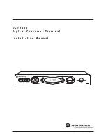
Отзывы: