Motorola solutions PELCO Sarix Professional 4, Instruction Manual
The Motorola Solutions PELCO Sarix Professional 4 is a cutting-edge surveillance camera system designed for professional use. To ensure optimal functionality, make sure to download the free Instruction Manual from manualshive.com. This comprehensive manual provides detailed information on setup, operation, and troubleshooting of the product.
Share
Download


Reviews:
No comments
Related manuals for PELCO Sarix Professional 4
EF 24mm f/2.8 IS USM
Brand: Canon Pages: 2
EF14mm f/2.8L II USM
Brand: Canon Pages: 2
EF24-105MM F/4L IS USM
Brand: Canon Pages: 21
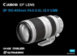
EF100-400mm f/4.5-5.6L IS II USM
Brand: Canon Pages: 21

Speedlite 600EX-RT
Brand: Canon Pages: 2
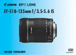
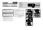
EF-S18-135mm f/3.5-5.6 IS STM
Brand: Canon Pages: 11
Speedlite 420EX
Brand: Canon Pages: 13
EF 70-200mm f/2.8L IS II USM
Brand: Canon Pages: 2
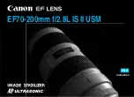
EF 70-200mm f/2.8L IS II USM
Brand: Canon Pages: 17
Macro Twin Light MT-26EX-RT
Brand: Canon Pages: 128
Speedlite 600EX-RT
Brand: Canon Pages: 372

EXPCMR-ALG-OZ-IC-1080PLE1-1227-250C-QD-15C-12.4
Brand: LARSON Pages: 4
EF-S10-18mm f/4.5-5.6 IS STM
Brand: Canon Pages: 16
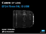
EF24-70mm f/2.8L USM
Brand: Canon Pages: 11

SCC-B9371
Brand: Samsung Pages: 1

SIR-60
Brand: Samsung Pages: 2

SNB-7001
Brand: Samsung Pages: 92

SDC-415 Series
Brand: Samsung Pages: 16


