Morris 57044, Operating Instruction
The Morris 57044 user manual is an essential Operating Instruction manual that provides comprehensive guidance for using the product. Easily download this manual for free from our website, ensuring efficient and hassle-free navigation. Unlock the full potential of your Morris 57044 with our easy-to-follow manual available at manualshive.com.
Share
Download


Reviews:
No comments
Related manuals for 57044

JT2007
Brand: Cojali Pages: 2
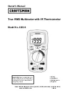
82024
Brand: Craftsman Pages: 13

82315
Brand: Craftsman Pages: 30

82141
Brand: Craftsman Pages: 36

82170
Brand: Craftsman Pages: 17

82139
Brand: Craftsman Pages: 40

82312
Brand: Craftsman Pages: 46

TMX-589
Brand: ES Pages: 23

34XR-A
Brand: Amprobe Pages: 73

1075
Brand: PeakTech Pages: 40

1020 A
Brand: PeakTech Pages: 36

2015
Brand: PeakTech Pages: 52

SNR-MPX-8E1-SFP
Brand: NAG Pages: 16

MD-6520
Brand: ICEL Pages: 95

PDM 300 C2
Brand: Parkside Pages: 150

Multiserver 500
Brand: Black Box Pages: 104

770E
Brand: Delton Pages: 11

89
Brand: Wavecom Pages: 16


