background image

R

0 2 1 , 7 2 5 , 1 *  6 2 / 8 7 , 2 1 6
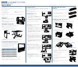
Operating Manual 

PulseNG

 Kit

Montronix GmbH

Telephone: +49 7062 6793 00

OPI-PulseNGKit-en-141106

Benzstr. 7

Fax: +49 7062 6793 10

Version: 2.01

D-71720 Oberstenfeld

E-Mail: [email protected]

Germany

Internet: www.montronix.de

Page 1 of 31

Certified CE

Operating Manual

PulseNG

 Kit

Summary of Contents for PulseNG Kit

Page 1: ...eNG Kit Montronix GmbH Telephone 49 7062 6793 00 OPI PulseNGKit en 141106 Benzstr 7 Fax 49 7062 6793 10 Version 2 01 D 71720 Oberstenfeld E Mail info montronix de Germany Internet www montronix de Pag...

Page 2: ...s 7 Personnel 8 Operation 8 Special Risks 8 IBU NG 9 Dimensions 9 Please observe 9 Connections 10 Communication Ports 11 LAN 11 USB 11 Serial interface 11 Diagnosis and LED signals 12 Sensor Connectio...

Page 3: ...9 Previous 19 Next 19 Load file 19 Save file 19 DSP 20 Text EL full view Text EL partial view 20 Export csv file 20 Config 21 Global Global settings 21 Plot 22 Sensor axes 22 Machine axes 22 Machine i...

Page 4: ...e 4 of 31 R 0 2 1 7 2 5 1 6 2 8 7 2 1 6 Operating Manual PulseNG Kit Description 27 IP address 27 Server port 27 Delete 27 Edit 27 Service 28 Software update 28 Firmware update 28 Default 28 Login Log...

Page 5: ...as listed in our BDS PulseNGKit en The software provided as user interface for the PulseNG monitoring system is titled PulseNG hmi PulseNG hmi runs under Microsoft Windows XP Windows 7 and Windows 8...

Page 6: ...e information available at the time of writing and believed to be correct The manual does not claim to cover all possible details or variations in hardware software installation or operation of the sy...

Page 7: ...must be permanently available for reference at the location of the system The operating manual must be read by any and all persons in charge of the following tasks at the machine machining center All...

Page 8: ...and maintenance instructions This includes all activities concerning general operations production changes tool and set up changes of the machine or its safety related equipment as well as inspections...

Page 9: ...fied professionals may perform the installation Labeling Function PE Ground 0 V GND voltage supply 24 V 24 V voltage supply IN5 Reset delete errors IN4 Monitor Active IN3 Bit 3 Value 4 of scenario num...

Page 10: ...T 2 LIMIT 3 Emergency cutout Operative Scenario Bit 1 Scenario Bit 2 Scenario Bit 3 MONITOR ACTIVE CONTROL ON ERROR RESET 0 V DC Supply 24 V DC Supply 0 V DC PE Figure 2 IBU NG wiring diagram Labeling...

Page 11: ...onnection of a Cat5 cable with straight outlet Serves to communicate with the user interface PulseNG hmi Can also be used for servicing LED 1 Communication signal yellow LED 2 Activity signal green LE...

Page 12: ...ff Device ready Device not ready IN1 IN5 yellow continually on Shows respective input status depending on whether contact is designated as normally open N O or normally closed N C OUT1 OUT5 red contin...

Page 13: ...manner that damages to the sensor its cable or the extension cable will be avoided The PulseNG Sensor must be firmly connected to the machine in order to guarantee flawless transmission of acceleratio...

Page 14: ...nts or vibrations do not cause splicing or friction Leave as much cable length hanging loose as is necessary to guarantee sufficient sag so as not to exert any pull on the cable in the event of moving...

Page 15: ...directly obtain connection with the IBU NG if you are using the factory default settings Software version The current PulseNG hmi software version and the required firmware can be checked by using the...

Page 16: ...0 10 0 10 20 0 2 4 6 8 10 0 2 4 6 8 10 0 2 4 6 8 10 0 2 4 6 8 10 19 8 9 5 1 3 2 HP 1 LP 1600 Z HP 1 LP 1600 Y HP 1 LP 1600 Hide Figure 5 PulseNG hmi initial window The following soft keys are availabl...

Page 17: ...the axes to fit the window Raw data view X Z Y 5 0 5 20 10 Adjust Filter data view Raw data view Statistics Y Axis Scaling m s X Axis Scaling s Figure 7 Raw data view Relates to the window with raw d...

Page 18: ...ile Sensor Event Log Back Monitoring Teaching Scenario Type Scenario Limit Limit Max Time date Axis X Y Z M Alarm Alarm Alarm Alarm Alarm Alarm Alarm Alarm Alarm Alarm Velocity Velocity Velocity Tempe...

Page 19: ...Y Axis HP 1 LP 1600 Alarm Alarm Alarm Monitoring Teaching Scenario Page Global Max Limit 1 Max Limit 3 Time Axis DSP Scenario Max Limit 2 Date Temperature Temperature Previous Next Load file Save file...

Page 20: ...03 18 09 07 33 2014 03 18 09 07 04 2014 03 18 09 06 51 2014 03 18 08 47 03 2014 03 18 08 45 38 2014 03 18 00 06 41 200 200 90 4 90 90 1600 90 0 Monitoring Teaching Scenario Text EL Graphics EL Text EL...

Page 21: ...anguage English X Axis X Axis Y Axis Z Axis Module Temperature Background DSP Monitoring Y Axis Z Axis N O Bit 5 Bit 4 Bit 3 Bit 2 Bit 1 N O N O N O N O N O N O N O N O N O never Teach mode Firmware v...

Page 22: ...s X Axis Y Axis Z Axis Module Background DSP Monitoring pulseNG 0 255 255 255 0 0 Select color OK Cancel Basic colors Hue Sat Val Red Green Blue Custom colors Add to Custom Colors Left mouse click on...

Page 23: ...well as About Qt Back Operating manual About About Qt Figure 17 Help Operating Manual 3 Operating Manual About About Qt Back Opens the operating manual as PDF file About 3 Operating Manual About Abou...

Page 24: ...LP filter Hz DSP Scaling Teach multiplier Emergency stop Alarm count Target value Limit 2 Enabled Limit Alarm off Window size Channel Limit type HP filter Hz DSP Delay ms Latched LP filter Hz DSP Scal...

Page 25: ...abled no signals are shown and monitoring is switched off Limit Shows the currently valid limit value Possible values 0 1 150 Alarm suppr When alarms are suppressed alarm outputs and emergency shut of...

Page 26: ...Low pass filter Possible settings from 0 1600 DSP Scale For Area DSP only Automatically set after teach operations Teach multiplier Figured into the raw signal during teach operations to determine the...

Page 27: ...Actif Interface IP address Port Connection Monitoring Teaching Scenario Figure 20 Sensor selection Add 3 Add Delete Edit OK Cancel Add a new IP address to the list pulseNG 192 168 1 241 3000 Communica...

Page 28: ...Software update Firmware update Back This soft key starts a firmware update Default 2 Help Scenario Select sensor Service Default OK Cancel Returns all software settings to factory defaults Login Log...

Page 29: ...uite 200 Ann Arbor MI 48108 USA 1 734 213 6500 1 734 213 6506 Montronix S r l Viale dei mille 101 27029 Vigevano PV ITALY 39 0 381 312020 39 0 381 319483 Montronix France Sarl Z I de l Eglantier 5 rue...

Page 30: ...r data view 17 Figure 7 Raw data view 17 Figure 8 Statistics 17 Figure 9 Save limits 18 Figure 10 Soft keys for event logs 18 Figure 11 Text EL 18 Figure 12 Graphics EL 19 Figure 13 Graphic shown with...

Page 31: ...l PulseNG Kit List of tables Table 1 IBU NG dimensions 9 Table 2 IBU NG labeling 9 Table 3 IBU NG labeling of wiring diagram 10 Table 4 Diagnosis and LED signals 12 Table 5 PulseNG sensor dimensions 1...

Reviews: