background image

ELECTRONICS FOR SPECIALISTS   ELECTRONICS FOR SPECIALISTS   ELECTRONICS FOR SPECIALISTS   ELECTRONICS FOR SPECIALISTS

Mehrkanal-Netzwerk-Rekorder 
zur Videoüberwachung
Multi-Channel Network Recorder 
for Video Surveillance
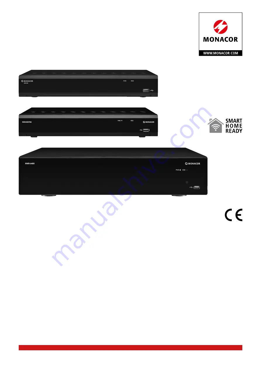
IOR-204

Bestell-Nr. • Order No. 18.9130

IOR-208

Bestell-Nr. • Order No. 18.9140

IOZ-204BV

Bestell-Nr. • Order No. 18.9150

IOZ-204DV

Bestell-Nr. • Order No. 18.9160

IOZ-408BV

Bestell-Nr. • Order No. 18.9170

IOZ-408DV

Bestell-Nr. • Order No. 18.9180

NWR-801POE

Bestell-Nr. • Order No. 18.0002

NWR-1608POE

Bestell-Nr. • Order No. 18.0001

NWR-3216POE

Bestell-Nr. • Order No. 18.0107

NWR-6400

Bestell-Nr. • Order No. 18.0176

BEDIENUNGSANLEITUNG   

Software-Version 8

INSTRUCTION MANUAL   

Software Version 8

Summary of Contents for IOR-204

Page 1: ...rder No 18 9130 IOR 208 Bestell Nr Order No 18 9140 IOZ 204BV Bestell Nr Order No 18 9150 IOZ 204DV Bestell Nr Order No 18 9160 IOZ 408BV Bestell Nr Order No 18 9170 IOZ 408DV Bestell Nr Order No 18 9180 NWR 801POE Bestell Nr Order No 18 0002 NWR 1608POE Bestell Nr Order No 18 0001 NWR 3216POE Bestell Nr Order No 18 0107 NWR 6400 Bestell Nr Order No 18 0176 BEDIENUNGSANLEITUNG Software Version 8 I...

Page 2: ......

Page 3: ...rlich Bitte lesen Sie die Anleitung vor dem Betrieb gründlich durch und heben Sie sie für ein späteres Nachlesen auf Der deutsche Text beginnt auf der Seite 4 Multi Channel Network Recorder These instructions are intended for installers and operators with basic knowledge in surveillance technology If the recorder is to be connected to a network knowledge in network technology is additionally requi...

Page 4: ... 6 Alarmeingänge konfigurieren 15 6 6 7 Alarm bei voller Festplatte Schreibfehler 16 6 6 8 PTZ Steuerung über die RS 485 Schnittstelle 16 6 6 9 Passwörter und Nutzer verwalten 16 6 6 10 Intelligente Bildanalyse 17 6 6 11 Werkseinstellung 18 6 6 12 Rekorder Konfiguration speichern 18 7 Bedienung 18 7 1 Bediensperre 18 7 2 Benutzerwechsel 19 7 3 Live Überwachung 19 7 3 1 Bildausschnitt vergrößern 19...

Page 5: ... Sollen die Geräte endgültig aus dem Betrieb genom men werden entsorgen Sie sie gemäß den örtlichen Vorschriften 2 Wichtig vor der Fahrt zum Installationsort Die Kameras der IOC Serie sind optimal auf die Rekorder ab gestimmt und brauchen nicht vorkonfiguriert zu werden Andere Kameras müssen eventuell vor dem Anschluss an den Rekorder vorkonfiguriert werden IP Adresse und Steuer protokoll weil son...

Page 6: ... 1 9 0 Kanalauswahl Zifferneingabe ALL Bildschirm aufgeteilt für die Ansicht aller Kanäle MENU Funktionsleiste aufrufen Funktionsleiste oder Menü ausblenden MUTE Ton ein aus SUBMENU Funktionsleiste aufrufen 2 Tastendruck Schnellauswahl Leiste für das angewählte Kamerabild aufrufen nach oben nach unten nach links rechts Parameterwert verringern erhöhen SEL angewählten Menüpunkt zum Einstellen aktiv...

Page 7: ...7 WAN Anschluss für einen Router 8 LINE IN Audioeingang für den Audiorückkanal von Kameras mit einem Audioausgang 9 AUDIO OUT Audioausgang für das Mikrofonsignal der Kamera die in der Live Überwachung angewählt ist Kap 7 3 2 10 VGA VGA Anschluss für einen VGA Monitor 11 HDMI HDMI Ausgang für einen hochauflösenden Monitor 12 SENSOR ALARM nur bei den Modellen IOR 204 IOR 208 und NWR 801POE Sensor Al...

Page 8: ...et Für andere Anschlussmöglichkeiten liegt das Audiosignal des gewählten Kanals an der Cinch Buchse AUDIO OUTPUT 9 an 5 4 Alarmein und ausgänge Diese Anschlüsse erfolgen über die grüne Klemmleiste 12 oder bei den Modellen NWR 1608POE NWR 3216POE und NWR 6400 über die abziehbaren grünen Schraubklemmen 17 Die Alarmeingänge sind bei den Modellen IOR 204 IOR 208 und NWR 801POE mit SENSOR beschriftet u...

Page 9: ...er mit dem sich der gewünschte Name eingeben lässt Zum Löschen von Zeichen auf klicken Zum Betätigen des eingegeben Namens auf klicken und das Tastatur Fenster wird geschlossen 4 In der Zeile Neues Admin Passwort ein Passwort mit mindestens 6 Zeichen eingeben und dieses in der Zeile Passwort bestätigen wiederholen In der Zeile Pass wortstärke wird zu Ihrem Passwort die Sicherheitsstufe angezeigt B...

Page 10: ...ie Einstellmenüs Diese lassen sich über das Kachelmenü Kapitel 6 6 aufrufen 1 Um mit dem Assistenten den Rekorder zu konfigurieren auf Start Wizard klicken Es erscheint das Menü für die Netzwerk einstellungen 192 168 001 100 255 255 255 000 192 168 001 100 008 008 008 008 008 008 008 008 Web TCP 00080 00080 09000 00554 Inactive Inactive Inactive 09000 00554 TCP TCP 1 2 3 Client Rtsp Network Weiter...

Page 11: ...u können müssen diese zuvor in das Netzwerk eingebunden worden sein siehe Anleitung der Kamera b Kurze Zeit nach dem Aufrufen des Menüs IP Camera werden auf der linken Seite die im Netzwerk vorhan denen Kameras angezeigt Bei Bedarf kann mit der Schaltfläche Suche erneut nach Netzwerkkameras gesucht werden c Aus den vorhandenen Kameras auf der linken Seite die gewünschte durch Anklicken auswählen d...

Page 12: ...tartup Wizard Abb 6 11 Übersicht der wichtigsten Einstellungen 12 Die wichtigsten Einstellungen für die Inbetriebnahme sind damit durchgeführt Nach dem Einstellen unten links das Feld Dieses Fenster nicht das nächste Mal anzeigen an klicken damit der Einrichtungsassistent nach dem nächsten Einschalten nicht mehr aufgerufen wird Dann zum Been den des Assistenten auf Fertig klicken 6 4 Wichtige Eins...

Page 13: ...tellmenüs aufrufen 5 Mit der rechten Maustaste kann immer auf die vorherige Menüebene zurückgesprungen werden 6 Die Menüs blenden sich 1 Minute Werkseinstellung nach dem letzten Klick automatisch aus Änderung über Kachel System Menüpunkt Allgemein Kap 6 6 1 oder kön nen durch Klicken auf das oben rechts ausgeblendet werden 6 6 1 Allgemeine Einstellungen Gerätename Sprache Menüanzeigezeit Uhrzeit e...

Page 14: ...ion Kanal Auswahl des Kamerakanals Privat Zone aktivieren Einschalten der Maskierfunktion Bereich Einschalten von bis zu vier Masken Zum Ändern der Größe einer Maske deren untere rechte Ecke bei gedrückter linker Maustaste ver schieben Zum Verschieben einer Maske in deren Mitte die linke Maustaste gedrückt halten Übertragen Einstellung sichern 6 6 4 Bewegungserkennung einstellen Ab Werk ist die Be...

Page 15: ...igurieren Sind an den Kontakten SENSOR 12 bzw ALARM IN 17 Alarmsensoren Bewegungsmelder Lichtschranken etc an geschlossen die Alarmeingänge konfigurieren Das Kachel menü aufrufen und in der Kachel Alarm auf den Menüpunkt IO alarm setting klicken Local 1 10 s 30 s Local 2 10 s 30 s Local 3 10 s 30 s Local 4 10 s 30 s Default Kopiere Übertragen Alarm In Alarm Type Alarmton Alarm Out Kanal Aufnahmeze...

Page 16: ...okoll Auswahl des Steuerprotokolls der Kamera Menüpunkt Funktion Baudrate Auswahl der Datenübertragungsrate Bit Anzahl der Datenbits Stop Anzahl der Stoppbits Prüfung Art des Paritätsbits None keins Ungerade Sogar gerade Kennzei chen immer 1 Space immer 0 Adresse Adresse der Kamera um alle angeschlossenen Kameras separat steuern zu können Kopiere Die Einstellungen eines Kamerakanals für andere Kan...

Page 17: ...tics PID 2 Indoor 1 Outdoor 3 Outoor Alarm Übertragen Kanal Einst Switch Empfindlichkeit Scene Abb 6 27 Einstellungen für eine intelligente Bildanalyse 2 In der Kopfzeile PID LCD CC Statisitcs durch Ankli cken die gewünschte Analyse auswählen Es werden nur die Kanäle angezeigt dessen Kamera die gewählte Funktion auch unterstützt Menüpunkt Funktion Kanal Auswahl des Kamerakanals Einst Auf klicken u...

Page 18: ...hern und wieder aufrufen 1 Den Rekorder wie gewünscht konfigurieren 2 Einen externen Speicher an eine der USB Buchsen des Re korders anschließen 3 Das Kachelmenü aufrufen und in der Kachel System auf den Menüpunkt Wartungseinstellungen klicken 4 Im Menü Wartungseinstellungen Abb 6 29 auf Para meter Management klicken um das Untermenü zum Speichern aufzurufen 5 Auf Einst sichern klicken und in dem ...

Page 19: ...r ge klickt werden 7 3 Live Überwachung Nach dem Einschalten sind immer die Kamerabilder in der Live Ansicht zu sehen das Datum und die Uhrzeit werden stets unten angezeigt CH1 CH2 CH3 CH4 Camera Keine Kamera Keine Kamera Keine Kamera 20 09 2019 20 36 57 20 09 2019 20 36 54 20 09 2019 20 36 54 Lagertor 20 09 2019 20 36 54 Eingang Abb 7 6 Live Überwachung Je nach Modell und Einstellung sind untersc...

Page 20: ... Ton aus einschalten Kap 7 3 2 HD SD i 15 09 2019 14 27 38 Stream Switch für die Netzwerkkameras nur für die Live Überwachung relevant Main Stream hohe Auflösung jedoch große Daten mengen Sub stream geringere Auflösung aber auch geringere Datenmengen HD SD i 15 09 2019 14 27 38 Vorschau Richtlinie regelt die Prioritäten bei voller System auslastung für die Live Überwachung Realtime möglichst hohe ...

Page 21: ...hmen abspielen Abschnitt einer Aufnahme extern speichern Zum Einblenden des Wiedergabefensters entweder die Taste auf der Fernbedienung drücken oder mit der rechten Maustaste die Funktionsleiste einblenden dort ganz links über das Startmenü aufrufen und im Startmenü auf Suche klicken 24h 2h 1h 30m CH1 Normal IO PIR PID LCD SOD PD FD CC Sound Occlusion Manual CH2 CH3 CH4 CH5 CH6 CH7 CH8 00 00 02 00...

Page 22: ...hmen ggf eingrenzen z B Normal zeitgesteuert IO Manual manuell Bewegung Stream Type Main Stream oder Sub stream auswählen Kanal Auswahl der Kamerakanäle hier mindestens einen Kanal anwählen Hier klicken um die Aufnahmen im gewählten Zeit raum aufzulisten Feld Symbol Funktion Funktionsauswahl unten Reihenfolge Zeitliche Reihenfolge der Auflistung umkehren WÄHLEN Alle Aufnahmen zum Speichern an oder...

Page 23: ...der Formatierung erscheint der Hinweis Notice Formatierung erfolgreich OK Abb 7 19 Festplatte formatiert 6 Auf OK klicken und zum Schließen des Disk Managers auf klicken 7 10 Ereignisliste aufrufen Der Rekorder protokolliert alle Ereignisse wie z B Ein und Ausschalten des Rekorders Nutzerwechsel manuelle Auf nahme Wiedergabe einer Aufnahme Änderung von Einstel lungen und vieles mehr 1 Mit der rech...

Page 24: ...rt für den Nutzer nicht aktiviert ist kann ohne Passworteingabe auf Authenticate geklickt wer den 4 Wurde Ausschalten gewählt erscheint folgender Hin weis Warnung Die Aufnahme wurde erfolgreich gestoppt Sie können das Gerät jetzt sicher ausschalten Abb 7 23 Hinweis dass der Rekorder ausgeschaltet werden kann 5 Den Rekorder mit dem Wippschalter 14 auf der Rückseite ausschalten 8 Einblendungen und S...

Page 25: ... das Symbol tippen Abb 9 4 um die Anzahl der Fenster für die Kamerabilder auszuwählen 9 Rechts in der Mitte unter dem Symbol auf das Dreieck tippen um die Rekorderkanäle aufzulisten Damit die Kamerabilder in den Fenstern erscheinen müssen in der Auflistung die Kanalnamen auf farbigem Hintergrund an gezeigt sein wie Camera1 in der unteren Hälfte der folgenden Abb Anderenfalls auf den Kanalnamen tip...

Page 26: ...lungen Abb 9 6 Live Überwachung von einem Computer aus Ein rotes R Record im Bild signalisiert dass der Kanal auf dem Rekorder aufgezeichnet wird Menüpunkt Symbol Funktion Kopfzeile Live Live Überwachung Wiedergabe Aufnahmen wiedergeben Remote Einstellungen Einstellungen für den Rekorder Lokale Einstellungen Pfade für Aufnahmen auf dem Computer festlegen i Den Mauszeiger auf das Symbol schieben In...

Page 27: ...27 Deutsch ...

Page 28: ...rt integriert Allgemein Sicherheit Passwortschutz Schnittstellen 1 WAN RJ45 für Netzwerkanschluss 3 USB2 0 für Maussteuerung und externe Sicherung von Aufzeichnungen 1 HDMI für Monitoranschluss 1 WAN RJ45 für Netzwerk anschluss 1 USB 3 0 2 USB2 0 für Maussteuerung und externe Sicherung von Aufzeichnungen 1 HDMI für Monitoranschluss Stromversorgung für die Kameras 4 PoE jeweils 20W 8 PoE jeweils 20...

Page 29: ...wortschutz Schnittstellen 1 WAN RJ45 für Netzwerk anschluss 1 USB 3 0 2 USB2 0 für Maussteuerung und externe Sicherung von Aufzeichnungen 1 HDMI für Monitoranschluss 1 e SATA für externe Festplatte 1 RS 485 für PTZ Steuerung Stromversorgung für die Kameras 8 PoE jeweils 20W 16 PoE jeweils 20W optional z B mit POE 130MID od TPE TG80G Festplatten optional max 4 8 TB SATA II optional max 4 8 TB SATA ...

Page 30: ... times 41 6 6 6 Configuring alarm inputs 41 6 6 7 Alarm for full disk write error 42 6 6 8 PTZ control via the RS 485 interface 42 6 6 9 Managing passwords and users 42 6 6 10 Intelligent image analysis 43 6 6 11 Factory setting 44 6 6 12 Saving the recorder configurations 44 7 Operation 44 7 1 User lock 44 7 2 User change 45 7 3 Live surveillance 45 7 3 1 Magnifying an image section 45 7 3 2 Soun...

Page 31: ...ion definitely dispose of the units in accordance with local regu lations 2 Issues to be Taken Care of Prior to Going to the Installation Site The cameras from the IOC series are optimally matched to the recorders and do not have to be preconfigured It is possible that other cameras must be preconfigured IP address and control protocol before they are connected to the recorder because otherwise th...

Page 32: ...igit input ALL Split screen mode to display all channels MENU To call up the toolbar to hide the toolbar or the menu MUTE To unmute mute the sound SUBMENU To call up the toolbar second press of the button to call up the quick selection bar for the camera image selected Upwards Downwards To go to the left right to decrease increase parameter value SEL To activate the selected menu item for setting ...

Page 33: ... Connection for a router 8 LINE IN Audio input for audio return channel of cameras with audio output 9 AUDIO OUT Audio output for the microphone signal of the camera that has been selected in live surveillance chapter 7 3 2 10 VGA VGA connection for a VGA monitor 11 HDMI HDMI output for a high resolution monitor 12 SENSOR ALARM Only for models IOR 204 IOR 208 and NWR 801POE Sensor alarm inputs e g...

Page 34: ...itor For other connection options the audio signal of the channel selected is available at the RCA jack AUDIO OUTPUT 9 5 4 Alarm inputs and alarm outputs These connections are made by means of the green terminal strip 12 or for the models NWR 1608POE NWR 3216POE and NWR 6400 via the removable green screw terminals 17 The alarm inputs are marked as SENSOR on the models IOR 204 IOR 208 and NWR 801PO...

Page 35: ...nge the name click the field highlighted by a blue frame A window with a keyboard will appear where the name desired can be entered To delete characters click To confirm the name entered click the window with the keyboard will be closed 4 In the line New Admin Password enter a password with a length of at least 6 characters Re enter the password in the line Confirm Password In the line Password St...

Page 36: ...ter 6 6 1 To configure the recorder by means of the wizard click Start Wizard The menu for the network settings will appear 192 168 001 100 255 255 255 000 192 168 001 100 008 008 008 008 008 008 008 008 Web TCP 00080 00080 09000 00554 Inactive Inactive Inactive 09000 00554 TCP TCP 1 2 3 Client Rtsp Network Next Cancel Local Connection DHCP DNS1 DNS2 IP Address Subnet Mask Gateway DNS Port Protoco...

Page 37: ...s been called up the left side of the menu will list the cameras available in the network If required click the button Search to search for IP cameras again c To select a camera click the camera desired in the list on the left side of the menu d To select a free channel for the camera click the corre sponding line on the right side of the menu e Click the blue arrow in the centre of the menu the s...

Page 38: ...12 The most important settings for operating the recorder have now been made Click the field Don t show this window next time in the lower left the wizard will not be called up when you start the recorder the next time To terminate the wizard click Finish 6 4 Important setting for the surveillance set IOZ The sets IOZ 204BV IOZ 204DV IOZ 408BV IOZ 208DV are preconfigured in such a way that the cam...

Page 39: ...tton any time to return to the pre vious menu level 6 According to the factory settings the menus will be ex ited automatically one minute after the last click this can be changed via the tile System menu item General chapter 6 6 1 alternatively the menu can also be exited by a click on in the upper right corner 6 6 1 General settings device name language menu display time time etc Call up the til...

Page 40: ...the mouse pointer on the lower right corner of the mask and then drag the corner while you keep the left mouse button pressed To move a mask position the mouse pointer in the centre of the mask and then move the mask while you keep the left mouse button pressed Apply To save the settings 6 6 4 Setting the motion detection feature According to the factory settings the motion detection feature is en...

Page 41: ...larm inputs When alarm sensors such as motion detectors or photoelectric sensors are connected to the contacts SENSOR 12 or ALARM IN 17 configure the alarm inputs Call up the tile menu and then in the tile Alarm click the menu item I O Local 1 10 s 30 s Local 2 10 s 30 s Local 3 10 s 30 s Local 4 10 s 30 s Default Copy Apply Alarm In Alarm Type Buzzer Alarm Out Channel Post Recording Show Me Latch...

Page 42: ...ol protocol of the camera Menu item Function Baudrate Selection of the data transmission rate DataBit Number of data bits StopBit Number of stop bits Parity Type of the parity bit None Odd Even Mark always 1 Space always 0 Address Address of the camera to be able to control all cameras connected separately Copy To use the settings of a camera channel for addi tional channels Default To reset this ...

Page 43: ...6 27 Settings for intelligent image analysis 2 In the header PID LCD CC Statistics click the appro priate option to select the analysis type to be used Only the channels whose camera supports the function selected will be shown Menu item Function Channel To select a camera channel Setup Click to define up to 4 detection fields for LCD and CC up to 4 lines 1 Click the left mouse button to define th...

Page 44: ...B ports of the recorder 3 Call up the tile menu and then in the tile System click the menu item Maintenance 4 To call up the submenu for saving click Parameter Man agement in the menu Maintenance Fig 6 29 5 Click Save Settings The window Save Settings will be shown make all settings for saving and click OK The name DEVICE_Settings will be assigned to the config uration file 6 If applicable save di...

Page 45: ...wn in the live view the date and the time will always be inserted at the bottom of the image CH1 CH2 CH3 CH4 Camera No Camera No Camera No Camera 09 20 2019 20 36 57 Fig 7 6 Live surveillance Depending on the model and the settings a different number of fields for the camera images is available Each camera image is designated by the number of the cam era channel CH In addition a camera name e g Ca...

Page 46: ... 3 2 HD SD i 15 09 2019 14 27 38 Stream switch for IP cameras only relevant for live surveillance Mainstream high resolution high data volume Substream lower resolution lower data volume HD SD i 15 09 2019 14 27 38 The Preview Policy defines the priorities to be applied when system utilization has reached 100 Realtime highest frame rate possible lower image quality Balanced medium frame rate mediu...

Page 47: ...lbar and then in the toolbar click the first symbol HD SD i 15 09 2019 14 27 38 to the left to call up the start menu and finally in the start menu click Search 24h 2h 1h 30m CH1 Normal IO PIR PID LCD SOD PD FD CC Sound Occlusion Manual CH2 CH3 CH4 CH5 CH6 CH7 CH8 00 00 02 00 04 00 06 00 08 00 10 00 12 00 14 00 16 00 18 00 20 00 22 00 00 00 09 28 2019 07 16 48 09 28 2019 07 16 48 Channel Stream Ty...

Page 48: ... save the recordings selected on a USB flash drive for example To replay the recording highlighted by a blue frame to select click the start image with the left mouse button Browse Type To select the display mode of the list 7 7 4 Viewing different time sections of a recording at the same time To go through long recordings more quickly you can replay four different time sections of a channel in a ...

Page 49: ...u click Setup to call up the tile menu 2 In the tile System click the menu item Maintenance 3 The submenus Log Auto Reboot are available The submenu Log must be selected as shown in the following figure 00 00 00 23 59 59 CH4 CH4 1 3 Backup Search Channel Type TIME CON RECORD Log Load Default Upgrade Parameter Management Auto Reboot Playback Accout admin Login 10 13 2019 05 43 27 System System Star...

Page 50: ...orm the user that the recorder can be switched off 5 Switch off the recorder with the rocker switch 14 on the rear 8 Insertions and Error Messages Insertion Meaning No hard disk inserted chapter 5 1 Hard disk does not work correctly Hard disk not formatted chapter 7 9 Hard disk write protected Hard disk full To change the overwrite mode so that the oldest recordings can be overwritten In the disk ...

Page 51: ...edia Port 9000 User Name admin Password Save Fig 9 3 Window for adding a new device 6 Enter the user name and the password as saved in the recorder 7 Tap Save and then tap the symbol in the upper left of the header to close the disk manager 8 For remote surveillance tap the symbol in the symbol bar located at the bottom of the screen fig 9 4 to select the number of windows for the camera images 9 ...

Page 52: ...lick the square next to Remember password To establish the connection click Login 7 After login the view for live surveillance will appear in the header Live will be selected R R R R i MainStream SubStream MobileStream Live Playback Remote Settings Local Stettings Fig 9 6 Live surveillance from a computer R Record highlighted in red is inserted in the image to indicate that the channel is being re...

Page 53: ...53 English ...

Page 54: ...ted General information Security password protection Interfaces 1 WAN RJ45 for network connection 3 USB2 0 for mouse control and external storage of recordings 1 HDMI for monitor connection 1 WAN RJ45 for network connection 1 USB 3 0 2 USB2 0 for mouse control and external storage of recordings 1 HDMI for monitor connection Power supply for the cameras 4 PoE 20W each 8 PoE 20W each 8 PoE 20W each ...

Page 55: ...rd protection Interfaces 1 WAN RJ45 for network connection 1 USB 3 0 2 USB2 0 for mouse control and external storage of recordings 1 HDMI for monitor connection 1 e SATA for external hard disk 1 RS 485 for PTZ control Power supply for the cameras 8 PoE 20W each 16 PoE 20W each optional e g with POE 130MID or TPE TG80G Hard disks optional max 4 8 TB SATA II optional max 4 8 TB SATA II optional max ...

Page 56: ...MONACOR INTERNATIONAL GmbH Co KG Zum Falsch 36 28307 Bremen Germany Copyright by MONACOR INTERNATIONAL All rights reserved A 2041 00 01 02 2020 ...

Reviews: