background image

64001-7400 Hand Crimp Tool 

Doc No.  ATS-640017400 

Release Date: 05-21-07 

UNCONTROLLED 

COPY


Page 1 of 9 

Revision: A 

Revision Date: 05-21-07 
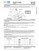
 

Hand Crimp Tool 

Operating Instruction and Specifications Sheet 

Order No. 64001-7400 

(Replaces 64001-3200) 


FEATURES 


A full cycle ratcheting hand tool ensures complete crimps 


Long handles for comfortable crimping with reduced crimping force 


3-nested tool eliminates the need for additional tools 


A precision user-friendly terminal locator holds terminals in the proper crimping position for 
each of the three nests 


SCOPE 

Products: Perma-Seal

  Ring Tongue, Spade Tongue, Hook Tongue, 3 and 4-Way 

Terminals. Butt Splices and Step Down Butt Splices 10

–22 AWG. 


Testing 

Mechanical 

The tensile test, or pull test, is a means of evaluating the mechanical properties of the 
crimped connections.  The following charts show the specifications for various wire sizes.  
The tensile strength is shown in pounds and indicates the minimum acceptable force to 
break or separate terminal from the conductor. 
 

Wire Size (AWG)  UL 

– 486 A  UL – 486 C 

22 

20 

13 

10 

18 

20 

10 

16 

30 

15 

14 

50 

25 

12 

70 

35 

10 

80 

40 


*UL - 486 A - Terminals (copper conductors only) 

*UL - 486 C - Butt Splices, Parallel Splices 

 
The following is a partial list of the product part numbers and their specifications that this tool 
is designed to run.  We will be adding to this list and an up to date copy is available on 
www.molex.com 
 

Wire Size: 18 

– 22 AWG 0.80 – 0.35 mm² 

Terminal No. 

Terminal 

Eng No. (REF) 

Terminal No. 

Mylar Tape 

Wire Strip Length 

Insulation Diameter 

Maximum 

In 

mm 

In 

mm 

19164-0003 

SA-221-10 

19164-0306 

.281 

7.14 

.235 

5.97 

19164-0004 

SA-222-14 

19164-0844 

.281 

7.14 

.235 

5.97 

19164-0005 

SA-226-38 

19164-0845 

.281 

7.14 

.235 

5.97 

19164-0006 

SA-235-06 


.281 

7.14 

.235 

5.97 

19164-0007 

SA-235-08 


.281 

7.14 

.235 

5.97 

19164-0008 

SA-235-10 


.281 

7.14 

.235 

5.97 

Summary of Contents for 64001-7400

Page 1: ...nections The following charts show the specifications for various wire sizes The tensile strength is shown in pounds and indicates the minimum acceptable force to break or separate terminal from the conductor Wire Size AWG UL 486 A UL 486 C 22 8 8 20 13 10 18 20 10 16 30 15 14 50 25 12 70 35 10 80 40 UL 486 A Terminals copper conductors only UL 486 C Butt Splices Parallel Splices The following is ...

Page 2: ...64 0022 SB 223 06 281 7 14 235 5 97 19164 0023 SB 224 06 281 7 14 235 5 97 19164 0024 SB 224 08 281 7 14 235 5 97 19164 0025 SB 225 10 19164 0940 281 7 14 235 5 97 19164 0026 SB 225 14 19164 0308 281 7 14 235 5 97 19164 0027 SB 225 56 19164 0309 281 7 14 235 5 97 19164 0028 SB 227 06 19164 0948 281 7 14 235 5 97 19164 0029 SB 227 08 19164 0949 281 7 14 235 5 97 19164 0030 SB 227 10 19164 0950 281 ...

Page 3: ...310 7 87 19164 0066 SC 230 14 19164 0317 438 11 12 310 7 87 19164 0067 SC 230 56 19164 0318 438 11 12 310 7 87 19164 0068 SC 240 38 19164 0857 438 11 12 310 7 87 19164 0069 SC 241 06 438 11 12 310 7 87 19164 0070 SC 241 08 438 11 12 310 7 87 19164 0071 SC 241 10 438 11 12 310 7 87 19164 0072 SC 268 10 438 11 12 310 7 87 19164 0073 SC 268 14 438 11 12 310 7 87 19164 0074 SC 2YCX N A 438 11 12 310 7...

Page 4: ...rminal No Terminal Eng No REF Terminal No Mylar Tape Wire Strip Length Insulation Diameter Maximum In mm In mm 19164 0077 SCB 646 19164 0582 281 7 14 300 7 62 OPERATION Open the tool by first closing the jaws sufficiently for the ratchet mechanism to release Crimping Terminals 1 Push in on the locator clamp to lift and position the nose of terminal under the clamp and push against the shoulder wit...

Page 5: ... the locator knob and slide locator all the way out away from crimp jaws When crimping the second end of a butt splice the locator assembly must be removed See Figure 5 1 Position the butt splice centered over the appropriate crimp pocket 2 Partially close the tool to hold the butt splice in place 3 Insert the properly stripped wire into the butt splice The end of the wire should butt against the ...

Page 6: ...or jammed in a partially closed position Do Not force the handles open or closed The tool will open easily by turning the ratchet release screw See Figure 7 Tool Calibration A Certificate of Calibration see last page was supplied with the tool To verify calibration of this tool pin gauge measurements should be taken in each conductor nest and compared to this chart The tool should be lubricated be...

Page 7: ...40017400 Release Date 05 21 07 UNCONTROLLED COPY Page 7 of 9 Revision A Revision Date 05 21 07 Hand held crimping tools are intended for low volume prototyping or repair requirements only Caution Repetitive use of this tool should be avoided ...

Page 8: ...ase Date 05 21 07 UNCONTROLLED COPY Page 8 of 9 Revision A Revision Date 05 21 07 PARTS LIST Item Number Order Number Description Quantity 64001 7400 Hand Crimp Tool Figure 7 1 64001 7475 Locator Assembly 1 Figure 7 RATCHET RELEASE SCREW 1 M4 X 30mm SHCS ...

Page 9: ...tor Nest 1 __ 090 097____Actual _____________ Range Conductor Nest 2 __ 110 118____Actual _____________ Range Conductor Nest 3 __ 156 166____Actual _____________ Technician________________________ Date of Calibration ___________________ mericas Headquarters e Illinois 60532 U S A 00 78MOLEX erinfo molex com Far East North Headquarters Yamato Kanagawa Japan 81 462 65 2324 feninfo molex com Far East...

Reviews: