MODSTER MINI CITO, User Manual
Get ready to unleash the power of your Modster Mini Cito with our comprehensive user manual. This manual covers everything you need to know about your product, from setup to troubleshooting. Download it for free from manualshive.com and make the most of your Modster Mini Cito experience.
Share
Download


Reviews:
No comments
Related manuals for MINI CITO
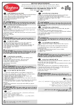
200
Brand: Baghera Pages: 3

22 52 23
Brand: ModelCraft Pages: 8

69000020
Brand: PR RACING Pages: 26

05 Corvette C6
Brand: REVELL Pages: 12

K-1300
Brand: Kawada Pages: 14

PirateMT Sport
Brand: Ofna Racing Pages: 15

Go! Cans XC6381
Brand: EB Excalibur Pages: 4

BLAZING TRACTOR
Brand: Moni Pages: 23

PistenBully 400 4F
Brand: Kässbohrer Pages: 164

X-Terminator 2e
Brand: XTM Racing Pages: 60

RAIL
Brand: XTM Racing Pages: 72

Kids Ride-On Mercedes-Benz AMG G63
Brand: Rovo Kids Pages: 24

Audi R8
Brand: Reely Pages: 2

AW16-H
Brand: allen Pages: 78

INFERNO MP7.5 Sports2 readyset
Brand: Kyosho Pages: 16

RC18B2
Brand: Associated Electrics Pages: 30

Z-Scale Ford C Series Truck Kit
Brand: Eaelec Pages: 2

FEBER XStorm BRAVO HIGH SPEED
Brand: Famosa Pages: 2


