background image

1

MCP15-500.9

October, 2020

INSTALLATION AND SERVICE MANUAL

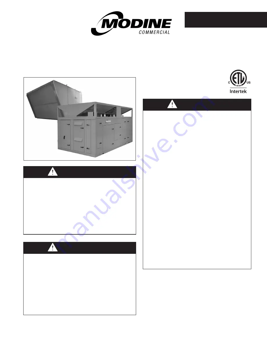
commercial packaged ventilation system units

model MPR 

(for units with 24 digit model numbers)

MCP15-500.9

5H0816400000

Inspection on Arrival

1.  Inspect unit upon arrival. In case of damage, report it 

immediately to transportation company and your local 

factory sales representative.

2.  Check rating plate on unit to verify that power supply meets 

available electric power at the point of installation.

3.  Inspect unit upon arrival for conformance with description 

of product ordered (including specifications where 

applicable).

THIS MANUAL IS THE PROPERTY OF THE OWNER. 

PLEASE BE SURE TO LEAVE IT WITH THE OWNER WHEN YOU LEAVE THE JOB. 


Improper installation, adjustment, alteration, 

service or maintenance can cause property 

damage, injury or death, and could cause 

exposure to substances which have been 

determined by various state agencies to cause 

cancer, birth defects or other reproductive 

harm. Read the installation, operating and 

maintenance instructions thoroughly before 

installing or servicing this equipment.

WARNING


This unit contains R-410A high pressure 

refrigerant. Hazards exist that could result in 

personal injury or death. Installation, 

maintenance, and service must only be 

performed by an HVAC technician qualified in 

R-410A refrigerant and using proper tools and 

equipment. Due to much higher pressure of 

R-410A refrigerant, DO NOT USE service 

equipment or tools designed for refrigerants 

other than R410A.

WARNING


FIRE OR EXPLOSION HAZARD

Failure to follow safety warnings exactly could 

result in serious injury, death or property  

damage. 
Be sure to read and understand the installation, 

operation and service instructions in this manual. 
Improper installation, adjustment, alteration, 

service or maintenance can cause serious 

injury, death or property damage.
Do not store or use gasoline or other 

flammable vapors and liquids in the vicinity  

of this or any other appliance. 


WHAT TO DO IF YOU SMELL GAS:

• Do not try to light any appliance.

•  Do not touch any electrical switch, do 

not use any phone in your building.

• Leave the building immediately.

•  Immediately call your gas supplier from  

a phone remote from the building.  

Follow the gas supplier’s instructions.

•  If you cannot reach your gas supplier, 

call the fire department.

Installation and service must be performed by 

a qualified installer, service agency or the gas 

supplier.

WARNING

Summary of Contents for MPR Series

Page 1: ...R 410A high pressure refrigerant Hazards exist that could result in personal injury or death Installation maintenance and service must only be performed by an HVAC technician qualified in R 410A refrigerant and using proper tools and equipment Due to much higher pressure of R 410A refrigerant DO NOT USE service equipment or tools designed for refrigerants other than R410A WARNING FIRE OR EXPLOSION...

Page 2: ...less the main power supply from the building to the unit is de energized 11 This unit contains R 410A high pressure refrigerant Hazards exist that could result in personal injury or death Installation maintenance and service must only be performed by an HVAC technician qualified in R 410A refrigerant and using proper tools and equipment Due to the high pressure of R 410A refrigerant DO NOT USE ser...

Page 3: ...rom the weather IMPORTANT 1 To prevent premature heat exchanger failure do not locate ANY gas fired appliances in areas where corrosive vapors i e chlorinated halogenated or acid are present in the atmosphere 2 A properly designed drain with trap must be installed immediately after the unit evaporator coil condensate drain pan connection Failure to do so will result in condensate that cannot prope...

Page 4: ... cover Units are designed for installation on non combustible surfaces with the minimum clearances shown in Figures 4 1 and 5 1 6 On units that have fresh air openings a method must be provided to prevent water and debris from entering the unit such as a rainhood which is available as an accessory from Modine Where possible install the unit so that the inlet is not facing into the prevailing wind ...

Page 5: ... alternate coil replacement direction k The minimum recommended clearance for service is 36 For service clearances less than shown applicable local code requirements must be followed If the ability for future condenser coil replacement is desired the minimum clearance must be from the end panel of the condenser not the end of the inlet hood 102 for B Cabinet sized units 112 for C Cabinet sized uni...

Page 6: ...o prevent damage WARNING Failure to follow proper lifting instructions and applicable safety procedures could result in property damage serious injury or death Lifting should only be done by a qualified rigging company Use ALL lifting points Test lift to ensure proper balance and rigging Never lift in high winds General Rigging Instructions Roof Curb Installation An optional roof curb is available...

Page 7: ...nections to the electric power supply and remote control circuits Connect the gas lines to the unit heating compartment Seal all utility line clearance holes on the unit after connections are completed so they are watertight Duct Installation 1 The unit is designed to accept 90 flanged ductwork on both the supply and return air openings Refer to the roof curb or the unit base dimensional drawings ...

Page 8: ...ctions air could be drawn through the drain pipe and into the system or could back up into the drain pan The drain is located on the suction side of the main supply air fan resulting in a negative pressure relative to outside the unit cabinet The trap height must be at least 6 to account for maximum negative pressure including allowance for dirty filters Note that the trap height is the difference...

Page 9: ...igital Control Wire Lengths 6 Depending on the configuration of the unit controls there may be sensors that are field installed Review the unit ordered to verify that the sensors supplied match the configuration of the unit The following are sensors that may be included for field installation Supply Air Temperature Sensor This sensor is required on all units and should be mounted in the supply air...

Page 10: ... field installed accessory the detector should be mounted in the supply air or return air ductwork For further instructions on the above sensor s refer to the installation instructions that shipped with the sensor s 7 If the unit is a C Cabinet sized unit with a Modine supplied Energy Recovery Module Model ERM the wiring connection between the MPR unit and the ERM unit must be made by extending th...

Page 11: ...e 11 1 l D Cabinet units consist of two furnaces that together total the value shown in Table 11 1 for sizes up to 800 000 Btu hr For sizes over 800 000 Btu hr the unit consists of four furnaces that together total the value shown in Table 11 1 n Capacities based on gas pressure up to 14 W C through Schedule 40 pipe with a pressure drop of 0 5 W C for Propane gas with a specific gravity of 1 50 Ta...

Page 12: ... kits refer to Literature MCP15 574 Installation Instructions Extended Vent Kit Model MPR Gas Heat otherwise install the vent terminal s as shown in Figure 12 1 When the terminal s have been installed proceed to the Start Up section Section B Non Condensing D Cabinet Furnaces Review Table 12 1 to verify this is the correct section for the unit and furnace type installed If not refer to the proper ...

Page 13: ...ert large diameter inner vent pipe assembly into the flexible rubber coupling on the left side power exhaust outlet Tighten the clamp on the flexible coupling to secure the vent pipe Step 3 Insert large diameter outside vent pipe termination through enclosure wall grommet and into the interlocking joint of the inner vent pipe assembly from Step 2 Step 4 Verify that the bird screens are inserted in...

Page 14: ...outlet Tighten the clamp on the flexible coupling to secure the vent pipe Step 2 Verify that the bird screen is inserted in the termination elbow and that the vent terminal elbow is oriented to exhaust straight down Step 3 Install the vent terminal with bird screen for the non condensing furnace on one side of the unit and secure with screws provided Caulk the mating surface before attaching Step ...

Page 15: ...erature 75 561 7 For proper operation the traps must be primed with water The traps must be installed with the higher side connected to the heater and the lower side connected to the drain 8 If there is an opportunity that the temperature in the space will fall below freezing during non operating periods the condensate drain systems and secondary heat exchanger must be completely drained to preven...

Page 16: ...tional Factory Installed Freeze Stat When equipped with the optional Coil Freeze Stat an auto resetting capillary type freeze stat see Figure 56 1 is factory installed immediately below and across the face of the hot water coil The stat is set to trip at 40 F adjustable and will automatically reset when the coil temperature rises 5 F above the setpoint If the stat has tripped the unit controls wou...

Page 17: ...17 MCP15 500 9 PAGE INTENTIONALLY LEFT BLANK ...

Page 18: ...ectrical and gas connections are weatherized 8 For C Cabinet sized units if the unit is installed with a Modine supplied Energy Recovery Module Model ERM verify the wiring connection between the MPR unit and the ERM unit has been properly installed If the unit is a B or D Cabinet sized unit with integral Energy Recovery the unit is already factory wired to the Energy Recovery section 9 For units w...

Page 19: ... switch Note Units include one blower door switch per access door one on B and C Cabinet two on D Cabinet that are factory installed inside the blower access section door s When a blower section door supply and or exhaust is opened the switch is opened and interrupts power to the low voltage circuit and de energizes the blower motor controller D Cabinet units also have the same switches on the eva...

Page 20: ...easure each motor individually Verify airflow volume and repeat steps above for further adjustment 7 If equipped with gas heat turn on the gas and initiate burner operation For guidance refer to the latest revision of the Controls Manual literature MCP74 525 8 Verify the temperature rise and supply air temperature of the heating section do not fall outside the range or exceed the maximums shown in...

Page 21: ...uires the blower to be in operation and the ductwork to be installed Setting the Air Flow Proving or Dirty Filter Switch 1 Ensure that the unit filters are clean Replace if necessary 2 Using the Modine Control System controller interface start blower operation 3 Turn the pressure switch set screw clockwise until it stops 4 With the wires removed from the common and normally open terminals of the s...

Page 22: ... compressor discharge pressure and may flood the compressor with liquid This may result in compressor failure not covered under warranty CAUTION START UP PROCEDURE CONTINUED Checking Refrigerant Charge This unit contains R 410A high pressure refrigerant Hazards exist that could result in personal injury or death Installation maintenance and service must only be performed by an HVAC technician qual...

Page 23: ... Check the ignition control and gas valve for electrical operation 5 Check to make sure that the main gas valve opens while the supply fan blower is operating 6 Check the gas pressure at the INLET to the combination gas control valve refer to figures on pages 26 through 31 and adjust as needed to maintain 6 7 W C for Natural Gas 11 14 W C for Propane while the burners are operating at high fire Th...

Page 24: ...efly press the MODE button to enter the Checkout Test mode 4 When the Checkout Test mode is entered the control board will initiate a normal ignition sequence with the Firing Rate Input set to a simulated 10 0 VDC The simulated Firing Rate Input can be set to different 1 0 VDC step values from 10V to 2V A 10V signal will give maximum fire rate while a 2V signal will give the minimum fire rate Once...

Page 25: ...nd LED display 2 Briefly press the MODE button again to review the fault codes Up to 15 fault codes are stored and can be reviewed by pressing the UP or DOWN buttons Codes will be displayed followed by the number of days since the fault was detected D CABINET SIZE UNIT OVER 800 000 BTU HR D CABINET SIZE UNIT UP TO 800 000 BTU HR C CABINET SIZE UNIT ALL GAS HEAT SIZES SECONDARY A SECONDARY C SECOND...

Page 26: ...nd Item 2 on 80 efficiency furnace 5 Solid state ignition control board cover removed 6 Furnace control board cover removed 7 Vent differential pressure proving switch 8 Direct spark ignitor 9 Manifold pressure tap on manifold tee 10 Flame sensor 11 Manifold piping with gas orifices 12 Condensate drain float switch 94 efficiency furnace only 13 Compartment strip heater thermostat 94 efficiency fur...

Page 27: ...e proving switch 10 Direct spark ignitor 11 Manifold tee pressure tap 12 Flame sensor 13 Manifold piping with gas orifices 14 Condensate drain float switch 15 1 3 4 13 9 10 1 Power exhauster 2 Maxitrol EXA STAR modulating gas valve right hand furnace only 3 Main combination gas valve 4 High limit control 5 VB1200 primary furnace control board for right side furnace but located on left side of cabi...

Page 28: ...dden behind piping as shown 5 Solid state ignition control board cover removed 6 Furnace control board cover removed 7 Vent differential pressure proving switch 8 Direct spark ignitor 9 Manifold pressure tap on manifold tee primary furnace only 10 Flame sensor 11 Manifold piping with gas orifices 12 Heat exchanger tube drain tray with drain line 1 3 5 7 2 4 6 8 10 11 12 9 Primary Furnace Right Sid...

Page 29: ... D Cabinet Sized Units 900 000 Btu hr and Larger 81 Eff Secondary Furnace B k Primary Furnace k Secondary Furnace A k Secondary Furnace C k j Refer to Figure 25 3 for location of furnace positions k Refer to Figure 28 1 for idenfication of furnace components j Refer to Figure 25 3 for location of furnace positions k Refer to Figure 28 1 for idenfication of furnace components ...

Page 30: ... piping as shown 5 Solid state ignition control board 6 Furnace control board cover removed 7 Vent differential pressure proving switch 8 Direct spark ignitor 9 Manifold pressure tap on manifold tee primary furnace only 10 Flame sensor 11 Manifold piping with gas orifices 12 Heat exchanger tube drain tray with drain line 13 Cabinet strip heater 1 3 5 7 2 4 6 8 10 11 12 9 Primary Furnace Right Side...

Page 31: ...ondary Furnace A k Secondary Furnace C k j Refer to Figure 25 3 for location of furnace positions k For identification of furnace components refer to Figure 28 1 for the 81 efficient modules on the bottom and Figure 30 1 for the condensing modules on the top j Refer to Figure 25 3 for location of furnace positions k For identification of furnace components refer to Figure 28 1 for the 81 efficient...

Page 32: ...nt damage j If the unit is a C cabinet size and has energy recovery exhaust refer to the latest revision of literature MCP15 520 for the Start Up Procedure for the Model ERM Energy Recovery Module 7 Check the belt tension and sheave alignment for the exhaust blower 8 Most motors are permanently lubricated for long life and are identified as such on the motor nameplate Most blower bearings are perm...

Page 33: ... preheat assembly with controls power compartment 14 S Outside air filters 15 O Outside air filters dirty filter switch 16 S Blower door switch 17 S Outside air enthalpy sensor 18 S Exhaust fan motor 19 S Exhaust plenum fan 20 S Exhaust fan motor access 21 O Inlet hood 22 S Exhaust hood not shown on B Cabinet 23 S Economizer bypass damper actuator access Economizer bypass not available on D Cabine...

Page 34: ... pan drain connection 23 O Gas or electric heat module gas shown 24 O Gas heating high limit control standard if gas heat 25 O Gas heating power exhauster outlet standard if gas heat 26 O Gas heat auxiliary electric heat not pictured S standard O optional UNIT COMPONENT IDENTIFICATION LOCATION Figure 34 1 Blower Evaporator Filter Damper Sections j Figure 34 2 Condenser Section j 1 S Condenser fan ...

Page 35: ... 12 O Dirty filter pressure switch not shown 13 S O Outside air damper standard on units with outside air 14 S O Damper actuator standard on units with outside air 15 S O Mixed air temperature sensor standard on units with outside and return air dampers 16 S Outside air enthalpy sensor 17 O Return air damper 18 O Modulating damper actuator 19 O Return air enthalpy sensor 20 O Return air smoke dete...

Page 36: ...s for remote shutdown exhaust initiation and compressor 20 S Low voltage wiring terminal strip with ground terminals 21 S Condenser fan ground terminals 22 O Condensing gas heat option strip heater fuses 23 O Phase failure relay and fuses COMPRESSOR CONTROL PANEL LEFT SIDE 24 S Compressor circuit breakers 25 S Compressor contactors with auxiliary contact blocks AUXILIARY CONTROL PANEL RIGHT SIDE 2...

Page 37: ...arel Ultracap for EVD controller 19 O Carel pCOe microprocessor expansion module 20 O Four pole relay s for smoke detector 21 O Two pole relay s for remote shutdown exhaust initiation and compressor 22 S Low voltage wiring terminal strip with ground terminals 23 O Auxiliary Supplementary electric heat fuse holder 24 O Power exhaust motor fuse holder 25 O Convenience outlet transformer primary fuse...

Page 38: ... for smoke detector s and exhaust fan initiation 8 S Low voltage terminal strip 9 S Solid state relay unloader 10 S Carel PCO5 microprocessor controller 11 S Carel PCOe microprocessor expansion module 12 S Carel EVD electronic expansion valve controller Circuit 1 13 S Carel EVD electronic expansion valve controller Circuit 2 14 S Low voltage terminal strip 15 O GFCI convenience outlet S standard O...

Page 39: ... 22 18 20 23 24 12 S Compressor Circuit Breakers 13 S Compressor Contactors 14 O Main Factory Mounted Disconnect Switch 15 S Supply Fan Power Distribution Block Dual Blower 1 10HP 16 S Supply Fan VFD 1 Supply Fan VFD 2 for Dual Blower 15 or 20HP not shown 17 S Supply Fan Overloads Dual Blower 1 10HP 18 S Ground Lug 19 S Cabinet Cooling Device not shown RIGHT SIDE POWER PANEL 20 S Bus Bar Terminals...

Page 40: ...t for exact location CONDENSING SECTION FAN QUANTITY 2 FOR 7 AND 10 TON UNITS 3 FOR 13 15 AND 20 TON UNITS 4 1 5 LIFTING EYE BOLTS EACH CORNER OF UNIT ACCESSORY RAINHOOD AND BIRDSCREEN FIELD INSTALLED ACCESSORY GAS ELECTRIC HEAT OPTION COMPARTMENT ACCESS DOORS CONTROLS COMPARTMENT ACCESS DOOR APPROXIMATE AREA FOR SIDE GAS SERVICE ENTRANCE refer to Warning label on unit for exact location 133 75 32...

Page 41: ...100 00 54 00 3 50 3 50 UNIT ACCESS SIDE CONDENSING SECTION SIDE 2 00 DIA ELECTRICAL ENTRY HOLE 2 39 2 39 2 39 2 39 2 39 SUPPLY AIR OPENING LOCATION RETURN AIR OPENING LOCATION RETURN AIR DUCT CONNECTOR ACCESSORY OPTIONAL SUPPLY AIR DUCT CONNECTOR ACCESSORY OPTIONAL 10 62 28 25 36 36 14 00 35 00 44 25 INSIDE 1 75 1 03 1 03 1 75 1 75 1 75 8 23 3 22 47 75 93 75 90 25 INSIDE 1 12 14 0 OR 24 0 SEE SCHE...

Page 42: ... CONDENSING SECTION FAN QUANTITY 2 FOR 7 AND 10 TON UNITS 3 FOR 13 15 AND 20 TON UNITS ACCESSORY RAINHOOD AND BIRDSCREEN FIELD INSTALLED ACCESSORY GAS ELECTRIC HEAT OPTION COMPARTMENT ACCESS DOORS CONTROLS COMPARTMENT ACCESS DOOR APPROXIMATE AREA FOR SIDE GAS SERVICE ENTRANCE refer to Warning label on unit for exact location 4 1 LIFTING ANGLES EACH CORNER 2 1 LIFTING ANGLES EACH SIDE ENERGY RECOVE...

Page 43: ...RY HOLE 2 39 2 39 2 39 2 39 2 39 43 72 176 00 172 50 102 25 104 19 Table 43 3 Roof Curb Weight approx lbs Section Description Weight Roof Curb 14 Insulated 259 14 Uninsulated 266 24 Insulated 394 24 Uninsulated 401 Figure 43 2 Unit Roof Curb Dimensions inches DIMENSIONS B CABINET UNIT BASE ROOF CURB W ENERGYRECOVERY SUPPLY AIR OPENING LOCATION RETURN EXHAUST AIR OPENING LOCATION RETURN AIR DUCT CO...

Page 44: ...OT GAS REHEAT COIL SERVICE ACCESS PANEL APPROXIMATE AREA FOR SIDE ELECTRIC SERVICE ENTRANCE refer to Warning label on unit for exact location APPROXIMATE AREA FOR SIDE GAS SERVICE ENTRANCE refer to Warning label on unit for exact location CONDENSING SECTION FAN QUANTITY 2 FANS FOR 15 TON UNIT 3 FANS FOR 20 THRU 30 TON UNITS SUPPLY AIR BLOWER EVAPORATOR HOT GAS REHEAT COIL ACCESS DOOR FILTER DAMPER...

Page 45: ...SEE DETAIL A FOR DIMENSIONS FOR UNITS WITH HOT WATER HEAT HOT WATER PIPING ENTRANCE UNITS WITH HOT WATER HEAT ONLY HOT WATER PIPING EXIT UNITS WITH HOT WATER HEAT ONLY DETAIL A FOR UNITS WITH HOT WATER HEAT 2 53 111 28 13 77 6 60 Figure 45 1 Unit Base Dimensions inches Figure 45 2 Roof Curb Dimensions inches SUPPLY AIR OPENING LOCATION RETURN EXHAUST AIR OPENING LOCATION if applicable 1 12 14 0 OR...

Page 46: ... 97 60 104 25 LUGS GAS SERVICE ENTRANCE GAS SERVICE ENTRANCE 4 1 00 LIFTING LUGS EACH CORNER OF UNIT 4 TIE DOWN POINTS EACH CORNER OF UNIT APPROXIMATE AREA FOR SIDE ELECTRIC SERVICE ENTRANCE refer to Warning label on unit for exact location LOW VOLT CONTROLS COMPARTMENT ACCESS DOOR EVAPORATOR HOT GAS REHEAT COIL SERVICE ACCESS PANEL 100 51 100 75 BASE CONDENSINGSECTION FAN QUANTITY 4 FANS FOR 30 A...

Page 47: ...ED FOR ELECTRICAL ENTRY 8 00 10 00 9 00 6 00 Figure 47 1 Unit Base Dimensions inches Figure 47 2 Roof Curb Dimensions inches 91 75 171 50 SUPPLY AIR OPENING LOCATION 60 12 34 25 19 64 88 25 INSIDE 1 75 1 75 1 75 1 75 171 00 167 50 INSIDE 1 12 14 0 OR 24 0 SEE SCHEDULE 16 00 6 25 25 00 2 14 1 25 86 48 21 81 33 40 RETURN AIR DUCT CONNECTOR ACCESSORY OPTIONAL SUPPLY AIR DUCT CONNECTOR ACCESSORY OPTIO...

Page 48: ...ED ACCESSORY 103 07 CONDENSING SECTION 25 28 EXHAUST HOOD 42 37 CONDENSER SECTION ERM SECTION 306 10 126 81 101 53 BY PASS DAMPER REMOVABLE PANEL ASSY FA FILTER FA DAMPER ERM DOOR ASSY ERM CONTROL PANEL ASSY DOOR 99 61 40 58 15 50 LUGS 111 74 LUGS 120 94 LUGS 6 1 00 LIFTING LUGS 4 EACH CORNER OF UNIT 2 IN BETWEEN UNIT ERM SECTION GAS SERVICE ENTRANCE 8 TIE DOWN POINTS 4 EACH CORNER OF UNIT 4 IN BE...

Page 49: ...F BASE THAT CAN BE DRILLED FOR ELECTRICAL ENTRY 6 00 10 00 8 00 9 00 Figure 49 1 Unit Base Dimensions inches Figure 49 2 Roof Curb Dimensions inches 88 25 INSIDE 14 00 OR 24 00 SEE SCHEDULE 254 68 91 75 1 75 1 75 1 75 1 75 255 18 251 18 INSIDE 21 81 33 40 87 99 24 15 RETURN AIR DUCT CONNECTOR ACCESSORY OPTIONAL SUPPLY AIR DUCT CONNECTOR ACCESSORY OPTIONAL 19 64 34 25 16 00 60 12 12 13 86 48 25 00 ...

Page 50: ...1002 20HP 232 232 232 36 Wheel 21 B 1041 Power Option Deadfront Disconnect pick one None 0 0 0 48 Wheel 21 C 1200 60A 100A 5 5 5 36 Wheel 21 F 1013 200A 10 10 10 46 Wheel 21 G 1088 400A 10 58 Wheel 21 H 3083 600A 15 68 Wheel 21 J 3224 Convenience Outlet pick one None 0 0 0 74 Wheel 21 K 3348 Powered by Others 2 2 2 81 Wheel 21 L 3403 Powered by Unit 40 40 40 Exhaust Air Fan None 0 0 0 11 114 16 12...

Page 51: ...07 0 08 0 10 0 11 0 15 200MBH High Temp Rise 0 06 0 08 0 09 Low Temp Rise 0 10 0 11 0 13 0 16 0 21 0 27 0 34 250MBH High Temp Rise 0 09 0 11 0 14 Low Temp Rise 0 13 0 16 0 21 0 27 0 34 0 43 0 52 0 62 300MBH High Temp Rise 0 07 0 08 0 09 0 11 Low Temp Rise 0 09 0 12 0 14 0 17 0 20 0 23 400MBH High Temp Rise 0 11 0 14 0 17 Low Temp Rise 0 14 0 17 0 20 0 23 175MBH 0 10 0 13 0 16 0 19 0 22 0 26 0 34 0...

Page 52: ... 07 0 07 0 08 0 08 0 09 0 09 0 10 0 11 0 13 Gas Heat 300MBH 0 07 0 09 0 11 0 14 0 17 0 21 0 25 0 30 0 35 400MBH High Temp Rise 0 09 0 11 0 14 Low Temp Rise 0 14 0 17 0 20 0 24 0 28 0 33 0 37 0 43 0 48 0 54 500MBH High Temp Rise 0 14 0 18 0 21 Low Temp Rise 0 20 0 24 0 28 0 33 0 37 0 43 0 48 0 54 0 67 0 98 600MBH High Temp Rise 0 21 0 25 0 29 0 33 Low Temp Rise 0 37 0 42 0 46 0 51 0 56 0 61 0 71 0 ...

Page 53: ...21 0 27 0 34 0 43 500MBH High Temp Rise 0 09 0 14 Low Temp Rise 0 16 0 21 0 27 0 34 0 43 0 52 0 62 600MBH High Temp Rise 0 13 0 17 Low Temp Rise 0 15 0 17 0 20 0 22 0 25 0 28 0 32 0 35 0 39 800MBH High Temp Rise 0 17 0 21 0 25 Low Temp Rise 0 20 0 22 0 25 0 28 0 32 0 35 0 39 0 42 0 46 0 51 900MBH 0 51 0 64 0 79 1000MBH 0 64 0 79 0 96 1 15 1 35 1200MBH 0 53 0 63 0 73 0 84 0 96 1 09 1 22 1400MBH 0 7...

Page 54: ...nt procedures must be performed by a qualified service agency 4 Check that the supply voltage matches the unit supply voltage listed on the Unit Serial Plate Verify that all wiring is secure and properly protected Trace circuits to insure that the unit has been wired according to the wiring diagram 5 Check that fuses or circuit breakers are in place and sized correctly Fan Assembly Direct drive fa...

Page 55: ...can result in damage to the coil and or health hazards Cleaning solutions must not be corrosive or cause damage to copper tube aluminum fin or all aluminum coils Clean the coil from the leaving air side so that foreign material will be washed out of the coil rather than pushed further in Be sure to carefully read and follow the cleaning fluid manufacturer s recommendations before using any cleanin...

Page 56: ...ct the control wiring to the freeze stat terminals Figure 56 1 Optional Factory Installed Hot Water Coil Freeze Stat MAINTENANCE CONTINUED Duct Furnace When providing annual maintenance for the duct furnace keep the unit free from dust dirt grease and foreign matter Pay particular attention to 1 The power exhauster discharge opening and the combustion air inlet louvers 2 The main burner orifices a...

Page 57: ...binet for maintenance if desired The wheel should not be slid out more than 50 of the width to prevent the wheel from tipping out of the cabinet Energy Recovery Wheel Electric Preheat When providing annual maintenance for the electric preheat if equipped keep the unit free from dust dirt grease and foreign matter Pay particular attention to 1 The heating elements should be checked annually for cra...

Page 58: ...ck and replace 3 Loose wiring to motor 3 Check and tighten 4 Motor overloaded 4 Reset motor starter and check motor load 5 Improper supply voltage 5 Check and correct C Blower Not Turning or Turns Slow 1 See Problems A and B 1 See Problems A and B 2 Broken drive belt 2 Check and replace 3 Motor undersized for application 3 Contact Factory 4 Motor voltage too low 4 Check and correct 5 Supply power ...

Page 59: ...2 See Problem D 3 Thermostat not calling for heat 3 Check and wait or override 4 Limit switches are open 4 Check and correct 5 Overload relay is tripped 5 Check and correct 6 Failed heat modules 6 Check and replace J Gas Heat Not Functioning Properly 1 See Problem A 1 See Problem A 2 See Problem D 2 See Problem D 3 Thermostat not calling for heat 3 Check and wait or override 4 Limit switches are o...

Page 60: ... Limit input at connector J8 and fuse at F1 E03 Modulation Valve Failure The Valve Actuator did not reach a Park or Full On position E04 Air Sensor Failure Pressure Reading Low Includes air switch failure to open during pre purge switch check includes insufficient air lockout due to blocked vent E05 Air Sensor Failure Pressure Reading High Includes air switch failure to close during pre purge swit...

Page 61: ...relay failure 6 Reserved 7 Primary limit failure 8 Gas valve in test mode 9 Safety startup failed to validate inducer air path Normal and Warning Conditions Green Slow Standby no communication link established Rapid Standby in communication with Primary Bus 1 Call for heat no gas 2 Call for heat gas Yellow 2 Call for heat gas flame rod aged Rapid Retry Table 61 1 Furnace Secondary Control Board VB...

Page 62: ...te Model Number and Serial Number of the unit The Serial Plate is located on the door of the controls cabinet For a complete description of the model number see the Model Nomenclature on pages 63 66 Serial plates shown are examples and may vary slightly from what is on the actual unit s Refer to the unit s for the actual serial plates MODEL IDENTIFICATION SERIAL PLATES Figure 62 1 Serial Plate Exa...

Page 63: ...g FSC Dual Standard Efficiency FMP Dual High Efficiency Condensing FMC Dual Standard Efficiency FDP Quad Standard Efficiency FQP Quad High Efficiency Hybrid FQH Dual High Efficiency Condensing FDC 4 5 6 7 Furnace Input Rating 0150 150 000 Btu hr thru 1600 1 600 000 Btu hr See Next Column See Unit Nomenclature on page 65 8 Heat Exchanger 409 Stainless Steel Heat Exchanger S 9 Ignition System Direct...

Page 64: ...ot Gas Reheat No Hot Gas Reheat 0 Modulating Hot Gas Reheat 1 Modulating Hot Gas Reheat with E Coat 2 11 Condensor Arrangement VFD Head Pressure Control Microchannel Coils A Microchannel Coils with E Coat UV B Modulating EC Motor Head Pressure Control 30 40 Ton Microchannel Coils E Microchannel Coils with E Coat F Modulating EC Motor Head Pressure Control 52 60 Ton Microchannel Coils G Microchanne...

Page 65: ...C Cabinet Only 4 18 Nominal Heat Capacity No Heating N Electric ratings derated for 208V 3ph 10kW B 20kW D 1 20kW B C 40kW D A 30kW B 60kW D 3 40kW B C 80kW D B 50kW B 100kW D 5 60kW B C 120kW D C 70kW B 140kW D 7 80kW B C 160kW D D 100kW B C 200kW D E Gas 81 Thermal Efficiency 150 MBH 1 x 150 F 200 MBH 1 x 200 G 250 MBH 1 x 250 H 300 MBH 1 x 300 B 2 x 150 C J 400 MBH 1 x 400 B 2 x 200 C D K 500 M...

Page 66: ...an ANPA Direct Drive C 25 x 2 Dual Airfoil Fans ANPA Direct Drive J 23 Exhaust Fan Motor HP includes VFD None or Not Applicable for C Cabinet N 1 HP Q 1 1 2 HP R 2 HP S 3 HP T 5 HP U 7 1 2 HP V 10 HP W 15 HP X 20 HP Y 24 Energy Wheel Preheat None or Not Applicable for C Cabinet N 20kW nominal Electric 2 40kW nominal Electric 4 MODEL NOMENCLATURE MODEL MPR CONTINUED Table 66 1 Model Nomenclature Ma...

Page 67: ...67 MCP15 500 9 PAGE INTENTIONALLY LEFT BLANK ...

Page 68: ...R S REMEDY FOR BREACH AS LIMITED HEREIN SHALL BE LIMITED TO ONE YEAR FROM DATE OF SHIPMENT FROM SELLER FOR GAS FIRED PRODUCTS INSTALLED IN HIGH HUMIDITY APPLICATIONS AND UTILIZING STAINLESS STEEL HEAT EXCHANGERS BUYER S REMEDY FOR BREACH AS LIMITED HEREIN SHALL BE LIMITED TO TEN YEARS FROM DATE OF SHIPMENT FROM SELLER These warranties are issued only to the original owner user and cannot be transf...

Reviews: