Mitsubishi HC6800, User Manual
The Mitsubishi HC6800 is a high-quality projector, perfect for creating a cinematic experience at home. Enhance your movie nights with its vibrant colors and sharp image projection. For easy setup and optimizing performance, make sure to download the user manual for free from manualshive.com. Achieve the best results with this reliable device.
Share
Download


Reviews:
No comments
Related manuals for HC6800

Portable Series
Brand: BenQ Pages: 61

MP780 ST
Brand: BenQ Pages: 25

Innovate iPJ-AW250NM
Brand: Hitachi Pages: 3

LP-TW4001
Brand: Hitachi Pages: 10

LP-TW34001
Brand: Hitachi Pages: 22

Innovate iPJ-AW250NM
Brand: Hitachi Pages: 92

Innovate ED-X50
Brand: Hitachi Pages: 2

LP-EW5002
Brand: Hitachi Pages: 115

LP-WU3500
Brand: Hitachi Pages: 120

LP-TW3001
Brand: Hitachi Pages: 153

Innovate iPJ-AW250NM
Brand: Hitachi Pages: 303

X253 - CP XGA LCD Projector
Brand: Hitachi Pages: 1

PLC-SU20N
Brand: Sanyo Pages: 1

PLC-HF15000L - 15000 Lumens
Brand: Sanyo Pages: 1

PLC-HF10000L - 10000 Lumens
Brand: Sanyo Pages: 1

PLC-HF10000L - 10000 Lumens
Brand: Sanyo Pages: 1

PLC-LNS08
Brand: Sanyo Pages: 4
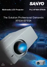
PLC-EF60A
Brand: Sanyo Pages: 2


